A control valve that holds position but delivers the wrong flow rate is not a working valve — it is a source of process deviation that your DCS loop controller will fight against, often without any alarm. Across power plant instrumentation systems, miscalibrated positioners and worn actuators are responsible for an estimated 30% of control loop performance degradation, contributing to fuel consumption inefficiency, steam temperature excursions, and load regulation errors that cost more than the valve itself is worth. Maintenance teams that structure their control valve work around actuator inspection, positioner calibration, leakage testing, stroke verification, and complete CMMS records catch these problems on a schedule — rather than during a load disturbance at 2 AM. This checklist covers every task, interval, and specification needed to maintain control valves to manufacturer and ISA standards, with direct integration into OxMaint's preventive maintenance module. Deploy this checklist in OxMaint free and automate your first control valve PM schedule today, or book a live demo to see how OxMaint manages instrumentation maintenance at scale.
Instrumentation & Controls · Checklist
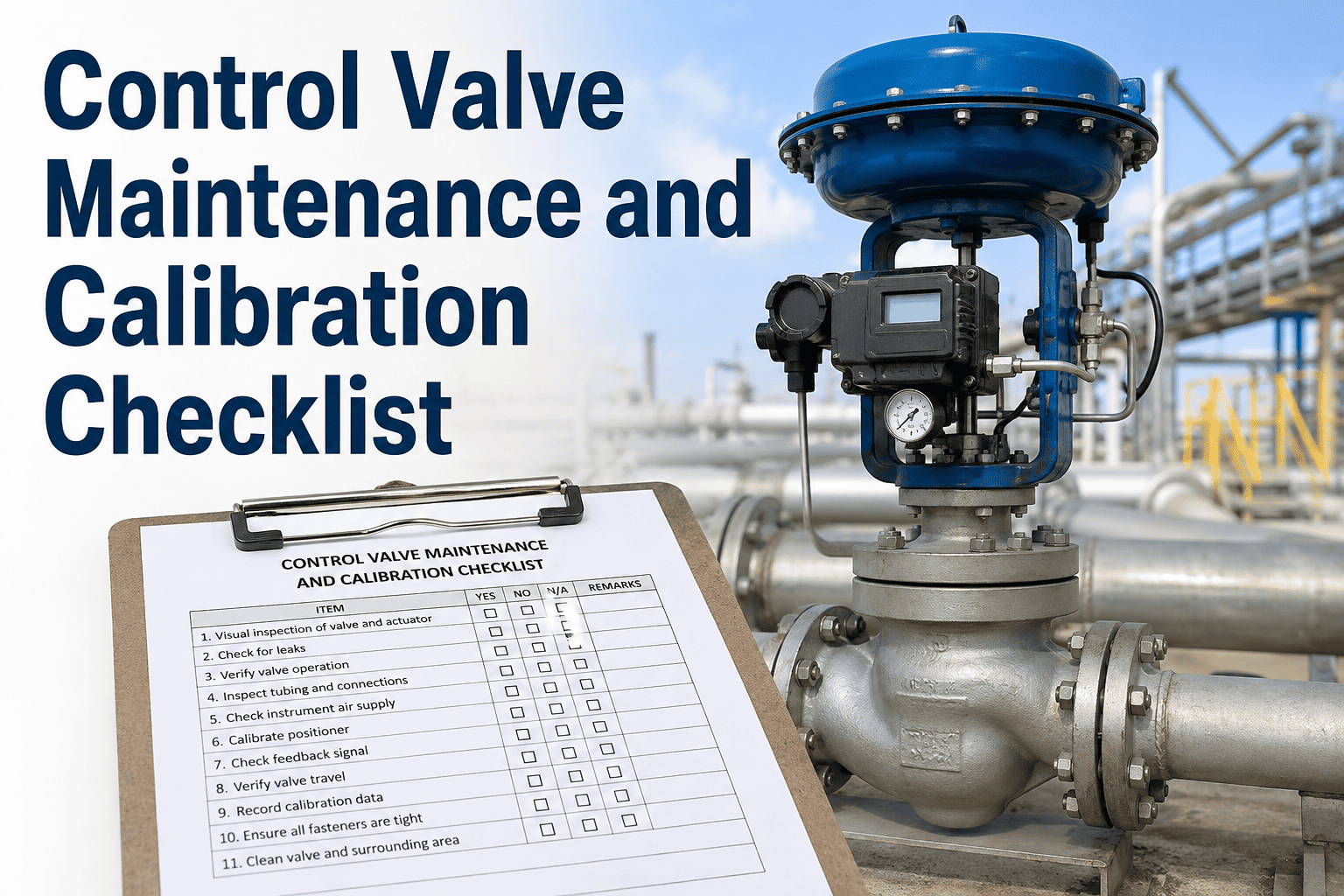
Control Valve Maintenance & Calibration Checklist
Actuator Inspection · Positioner Calibration · Leakage Testing · Stroke Testing · CMMS Records
30%
Control loop degradation from valve issues
±0.5%
Typical positioner accuracy after calibration
ANSI/FCI 70-2
Seat leakage class standard
ISA-75.13
Control valve performance test standard
Why Control Valves Fail Without Warning
Control valves degrade in ways that are invisible to plant DCS unless specific diagnostic tools are used. The failure patterns below represent the four most common causes of control valve underperformance in power plant applications — each with a distinct inspection method and checklist task.
35%
Actuator Problems
Pneumatic actuator diaphragm fatigue or rupture
Loss of spring pre-load — fail-safe position incorrect
Piston seal wear in double-acting actuators
Detection: stroke test + bench calibration
28%
Positioner Drift
Zero and span shift from temperature cycling
Feedback linkage wear — position signal error
Supply air quality degradation — moisture in pilot valve
Detection: 5-point calibration check
22%
Packing & Seat Leakage
Stem packing wear — external process leakage
Seat erosion from high-velocity steam or abrasive fluids
Plug/ball/disc erosion changing flow characteristic
Detection: seat leakage test per ANSI/FCI 70-2
15%
Instrument Supply Issues
Instrument air pressure below 4.5 bar — valve response degraded
Air filter-regulator plugging — pressure drop across regulator
I/P transducer failure — open loop or stuck signal
Detection: supply pressure check and I/P output test
Control Valve Maintenance Checklist
Monthly
Visual Inspection & Operational Check
Instrumentation Technician · In-Service Inspection
External Condition
Valve body and bonnet inspected — no visible process leakage at flanges or packing gland
Stem packing condition checked — no visible seepage or crystallization around stem area
Actuator housing inspected — no cracks, corrosion, or mechanical damage to casing
Positioner enclosure integrity confirmed — no moisture ingress, cover secured
Air supply tubing and fittings inspected — no kinking, abrasion, or loose compression fittings
Operational Verification
Control signal checked at positioner input — reading matches DCS output (4–20 mA or digital bus)
Valve position feedback verified — positioner feedback matches DCS indicated position
Instrument air supply pressure confirmed at 4.5–7 bar at positioner supply port
Air filter-regulator drain checked and purged — no accumulated moisture or oil
Valve response to manual DCS step change observed — no excessive hysteresis or deadband
Quarterly
Stroke Test & Positioner Performance Check
Instrument Technician · Coordinated with Operations
Stroke Testing
Full stroke test performed — valve stroked from 0% to 100% and back under DCS control
Travel time measured — opening and closing stroke times recorded and compared to baseline
Mechanical travel stops confirmed — valve reaches full open and full closed positions
Stem and plug checked for mechanical binding — smooth travel with no sticking at mid-stroke
Fail-safe position verified — actuator moves to correct fail position on air supply isolation
Positioner Calibration Check
5-point calibration check: apply 4 mA, 8 mA, 12 mA, 16 mA, 20 mA — record actual valve position at each
Hysteresis measured — upscale and downscale readings compared at each calibration point
Deadband measured — minimum input change required to initiate valve movement
Zero and span confirmed within ±1% of rated travel — adjust if outside tolerance
Digital positioner diagnostics reviewed if HART-enabled — record valve signature data
Semi-Annual
Seat Leakage Test & Packing Inspection
Process Isolation Required · Two-Person Task
Seat Leakage Test (ANSI/FCI 70-2)
Valve isolated from process — upstream and downstream block valves confirmed closed
Valve driven to fully closed position under full actuator loading
Upstream pressure applied per test specification — hydrostatic or pneumatic test
Leakage measured at downstream side — compared to ANSI/FCI 70-2 Class (II through VI) acceptance criteria
Leakage test result recorded in CMMS — flag for seat repair if Class IV or higher valve falls below Class
Packing & Stem Inspection
Packing gland torque checked — graphite packing follower nuts at OEM specified torque
Stem condition inspected — no pitting, scoring, or corrosion on polished stem surface
Stem packing emission test if fugitive emission monitoring required — TA Luft or EPA 40 CFR 60
Anti-rotation device (where fitted) confirmed intact — stem cannot rotate during actuator stroke
Packing replacement scheduled if seepage noted or packing at age limit per OEM data sheet
Annual
Full Calibration, Actuator Overhaul & CMMS Record Update
Valve Isolated & Depressurized · Qualified Technician Required
Actuator Overhaul
Actuator disassembled per OEM procedure — diaphragm, O-rings, and seals inspected and replaced per interval
Spring force verified — confirm spring rate against OEM datasheet; replace if set length out of specification
Yoke and stem connector inspected — wear in clevis pins and connector hardware measured and replaced if worn
Piston seals replaced for double-acting actuators — o-ring and backup ring condition assessed before replacement
Actuator bench tested post-reassembly — full travel confirmed at correct air pressure before reinstallation
Full System Calibration & Records
Full 11-point calibration performed — 0%, 10%, 20% through 100% in 10% steps, upscale and downscale
Calibration deviation curve plotted — maximum error recorded and compared to ±0.5% rated travel specification
I/P transducer output verified — 3–15 psi output confirmed against 4–20 mA input at each calibration point
As-found and as-left readings recorded in CMMS — calibration certificate issued and filed
Next calibration due date set in OxMaint — reminder scheduled automatically for technician assignment
Automate Every Control Valve PM Interval in OxMaint
OxMaint's preventive maintenance module automatically schedules monthly, quarterly, semi-annual, and annual control valve tasks, assigns them to calibrated technicians, captures as-found and as-left data, and generates audit-ready calibration records — all on mobile devices in the field.
Positioner Calibration: Step-by-Step Procedure
Tools Required
4–20 mA loop calibrator (HART-enabled preferred)
Calibrated pressure gauge (±0.1% accuracy)
Digital position indicator or ruler with mm scale
Laptop with HART communicator or ValveSight software
Pre-Calibration Requirements
Valve isolated from process — isolation confirmed by operations
Instrument air supply confirmed at correct pressure
Positioner in manual mode — DCS output disconnected
Previous as-found readings documented before any adjustment
Acceptance Criteria
Zero error: <0.5% of rated travel
Span error: <0.5% of rated travel
Hysteresis: <1% of rated travel
Deadband: <0.5% of input signal span
| Step |
Action |
Expected Result |
If Outside Tolerance |
| 1 |
Apply 4 mA (0% signal) — drive valve to full closed |
Valve at 0% ± 0.5% travel — record actual position |
Adjust zero pot or cam position on positioner |
| 2 |
Apply 20 mA (100% signal) — drive valve to full open |
Valve at 100% ± 0.5% travel — record actual position |
Adjust span pot or feedback arm length |
| 3 |
Repeat steps 1–2 until zero and span are stable — no further adjustment required |
Consistent 0% and 100% readings within tolerance |
Check feedback linkage for wear or backlash |
| 4 |
Apply 8 mA, 12 mA, 16 mA — record position at each upscale point |
25%, 50%, 75% ± 1% travel at each setpoint |
Check positioner characterization cam — replace if worn |
| 5 |
Reverse: apply 16 mA, 12 mA, 8 mA downscale — record positions |
Hysteresis <1% between upscale and downscale at each point |
Increase instrument air pressure; check for friction |
| 6 |
Record all as-left readings, sign calibration sheet, update OxMaint CMMS record |
Calibration certificate created with technician sign-off |
File non-conformance report if valve cannot be brought into tolerance |
ANSI/FCI 70-2 Seat Leakage Class Reference
| Class |
Test Medium |
Allowable Leakage |
Typical Application |
OxMaint Flag |
| Class II |
Air or water at 45–60°C |
0.5% of rated Cv |
Non-critical general service — bypass flows acceptable |
Log result — no action if within class |
| Class III |
Air or water at 45–60°C |
0.1% of rated Cv |
Standard industrial service — moderate sealing requirement |
Log result — schedule retest at 6 months if approaching limit |
| Class IV |
Air or water at 45–60°C |
0.01% of rated Cv |
Most power plant control valves — standard specification |
Flag for seat inspection if measured >0.008% Cv |
| Class V |
Water at maximum service pressure |
5×10⁻⁴ ml/min/psi/inch DN |
Critical isolation — boiler feed control, HP bypass |
Immediate work order if any measurable leakage at Class V spec |
| Class VI |
Nitrogen or air at 3.4–6.9 bar |
Bubble-tight — per seat diameter table |
Safety-critical tight shutoff — steam isolation |
Immediate work order — valve pulled for seat lapping or replacement |
CMMS Record Requirements for Control Valve Calibration
01
Asset Identification
Tag number, P&ID reference, loop number, valve manufacturer, model, trim material, and installed location. OxMaint stores this permanently on the asset record — no re-entry at each calibration.
02
As-Found Readings
All measured values before any adjustment. As-found data is the compliance record — it demonstrates what condition the valve was in when the technician arrived, independent of what was done next.
03
As-Left Readings
All measured values after calibration and adjustment. As-left data confirms the valve left service in a calibrated condition. Both as-found and as-left must be retained for audit — one without the other is incomplete.
04
Reference Equipment Used
Calibrator make, model, serial number, and current calibration certificate expiry date. Any reference instrument used for comparison must itself be traceable to national standards — NABL/NIST traceable.
05
Technician Sign-Off & Next Due Date
Technician name, qualification, signature, and date. Next calibration due date set and confirmed in OxMaint — automatic reminder generated to ensure no interval is missed.
Calibration Certificate Generation
OxMaint generates a complete, printable calibration certificate from data entered on the mobile app — no re-keying from paper to system.
Automated Interval Scheduling
As-left date automatically sets the next calibration due date. OxMaint creates the next work order and notifies the assigned technician before the deadline.
Out-of-Tolerance Escalation
If as-found readings fall outside tolerance, OxMaint flags the event for supervisor review and creates a linked corrective work order automatically.
Audit Export
Full calibration history for any valve, date range, or technician is exportable in PDF or CSV in a single click — ready for regulatory or internal audit at any time.
Set up your first valve calibration schedule in OxMaint free →
Frequently Asked Questions
How often should control valve positioners be calibrated in a power plant?
Most power plant control valves require positioner calibration verification quarterly, with full 11-point calibration annually or after any maintenance event that disturbs the feedback linkage. Valves on critical loops — turbine steam control, boiler drum level — should be verified more frequently. OxMaint assigns calibration intervals per valve criticality and auto-schedules accordingly.
Configure your calibration intervals in OxMaint free.
What is the difference between hysteresis and deadband in a control valve?
Hysteresis is the difference in valve position for the same input signal depending on the direction of travel — caused by friction and mechanical backlash. Deadband is the range of input signal change that produces no valve movement — caused by mechanical play in the feedback linkage or positioner pilot valve. Both are measured separately and have different correction methods. Acceptable limits per ISA-75.13 are typically <1% for hysteresis and <0.5% for deadband.
When should a control valve be pulled for shop repair versus repaired in-line?
Seat leakage exceeding the specified class, trim erosion causing a change in flow characteristic, and body wall thinning below minimum allowable all require the valve to be removed and repaired in a shop or by the OEM. Actuator diaphragm replacement, packing replacement, and positioner calibration can be done in-line with process isolation. OxMaint work order templates include pull-versus-in-line decision criteria for each failure mode.
Book a demo to see how OxMaint manages repair decisions in workflow.
What does a valve signature test reveal that a standard stroke test does not?
A valve signature (dynamic valve diagnostics on smart HART positioners) plots stem force versus travel across the full stroke — revealing friction, packing force, seat load distribution, actuator spring force, and stem seating. These characteristics are invisible in a standard stroke test, which only confirms that the valve moves. OxMaint stores valve signature files against the asset record for trend comparison over multiple calibration cycles.
What ANSI/FCI 70-2 leakage class do power plant control valves typically require?
Most power plant control valves — feedwater control, steam temperature, and load control — are specified at Class IV (0.01% of rated Cv). HP bypass and main steam isolation valves are typically Class V or VI — bubble-tight shutoff. The specified class is on the valve data sheet and must be verified at every seat leakage test.
Set seat leakage class per valve in OxMaint.
Deploy Your Control Valve PM Program in OxMaint Today
Pre-built control valve checklists, automated calibration scheduling, as-found / as-left data capture on mobile, and audit-ready calibration certificates — all in OxMaint's preventive maintenance module. Most instrumentation teams are fully live within one week.