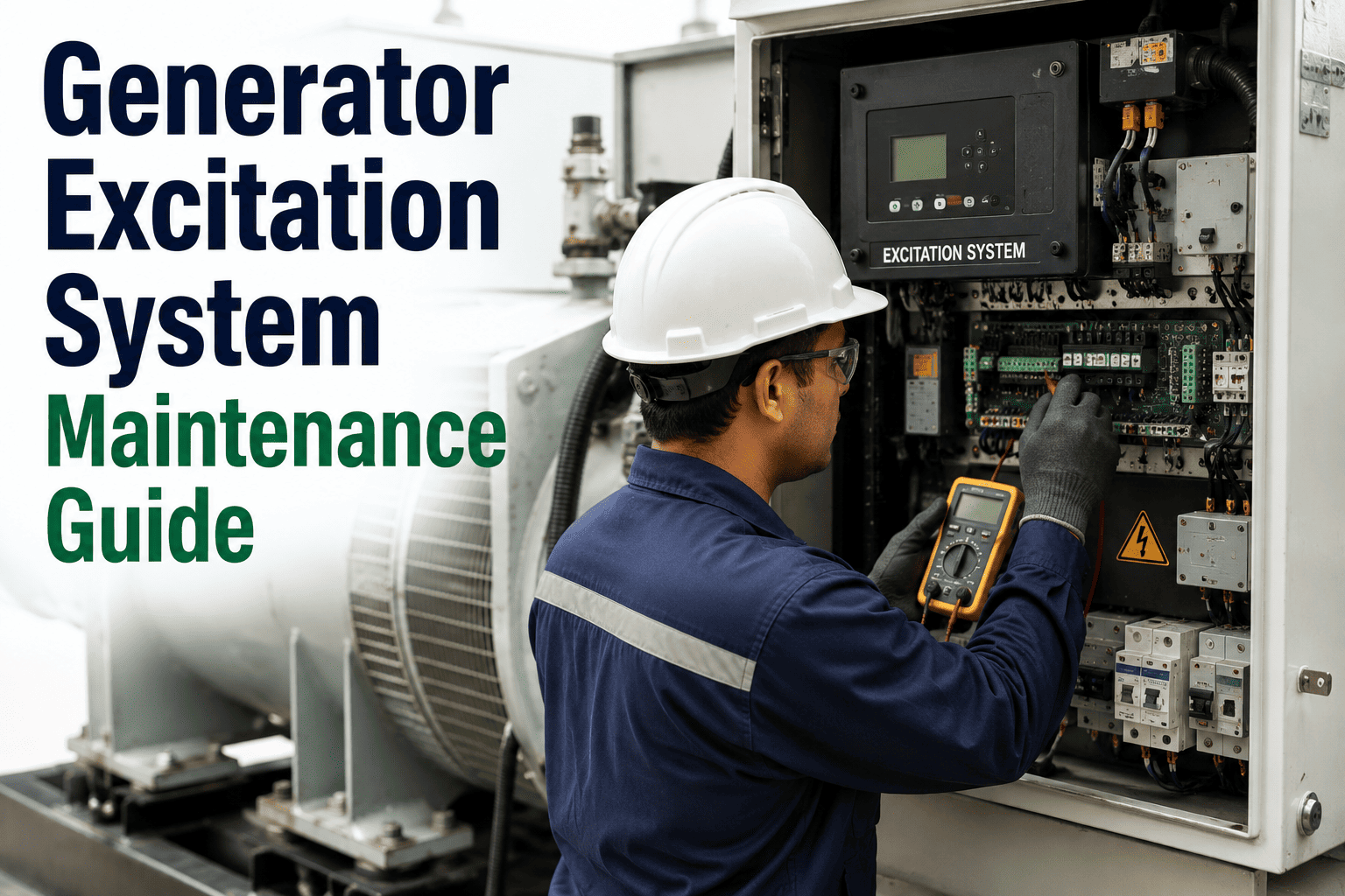
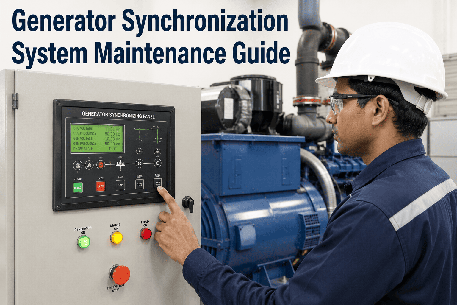
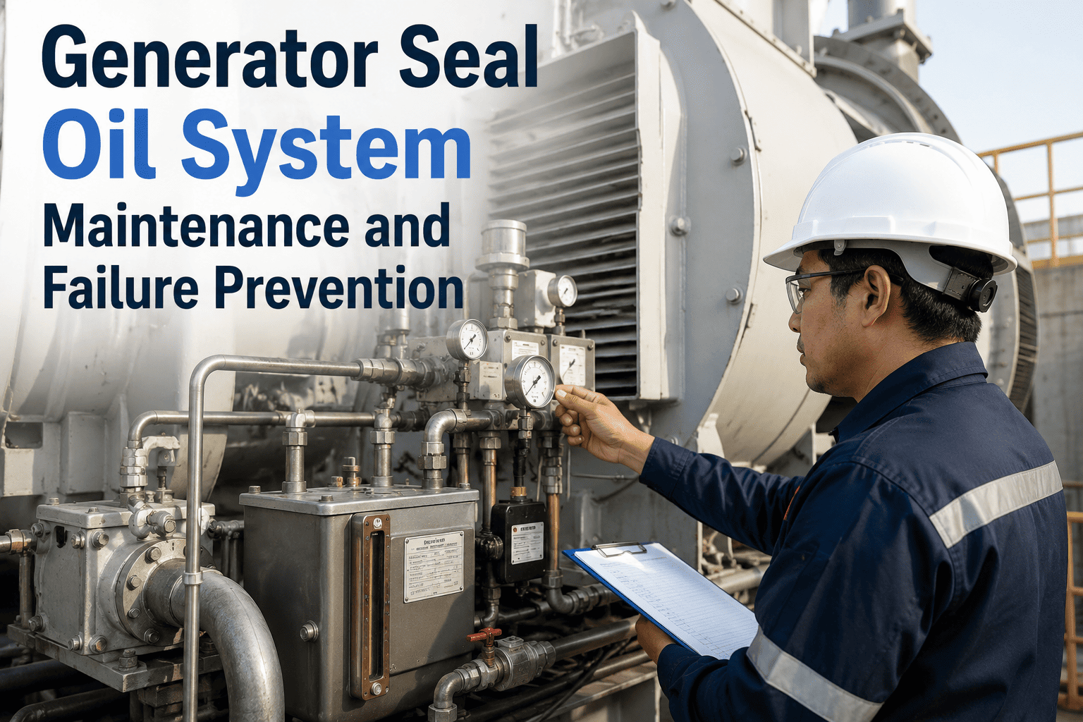
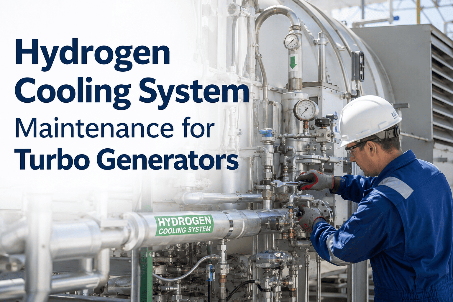
The excitation system is the part of a generator most operators only think about after it has already failed — right up until a sudden loss of field trips the unit offline and triggers a grid disturbance investigation. Brush wear, diode failures in brushless systems, and slip ring contamination all build up gradually, but the consequences arrive suddenly, often during a load swing when the AVR is working hardest to hold voltage. A structured inspection and monitoring program turns those gradual signs into planned work instead of an unplanned trip. OxMaint's asset management platform gives generator excitation systems the dedicated tracking they rarely get.
Why Excitation Systems Get Overlooked Until They Fail
Compared to the turbine and the generator stator, the excitation system is small, low-power, and easy to deprioritize on a maintenance plan dominated by larger rotating equipment. Yet a loss of excitation event can trip the unit, cause reactive power swings that stress neighboring units on the grid, and in severe cases lead to pole slipping. The asset deserves a maintenance program sized to its consequence, not its physical footprint.
1
Daily Visual Checks
Brush spring tension, slip ring surface condition, and AVR cabinet alarm status reviewed during routine rounds.
2
Weekly Trending
Field current, field voltage, and AVR response time logged and compared against the established baseline for the unit.
3
Quarterly Inspection
Brush wear measurement, diode testing on brushless systems, and slip ring contact resistance checked during a planned outage window.
4
Annual Overhaul
Full excitation system teardown, insulation resistance testing, and AVR calibration verification against OEM specification.
Brush-Type vs Brushless Excitation — Different Failure Modes, Different Checks
The maintenance approach for a generator excitation system depends heavily on whether it is a brush-type system with slip rings or a brushless rotating rectifier design. Each has a distinct dominant failure mode that the inspection program needs to target specifically.
Brush-Type Systems
Brush wear rate tracked against hours and current density
Slip ring surface glazing and grooving inspected visually
Brush spring tension verified to maintain consistent contact pressure
Carbon dust accumulation cleaned to prevent flashover risk
Brushless Systems
Rotating diode testing for open or shorted conditions
Surge suppression module condition verified during outages
Pilot exciter output checked against design parameters
Rotating rectifier wheel balance and connection torque verified
The Signals That Predict Excitation Failure
Both brush-type and brushless systems leave measurable warning signs before a trip occurs. The key is tracking these signals continuously rather than relying solely on a periodic manual inspection that might miss a fast-developing fault.
Field Current Instability
Erratic field current under steady load conditions often signals a developing diode or brush contact problem before it becomes a trip.
AVR Response Lag
Slower than expected voltage correction during load swings can indicate degrading control loop components or sensing issues.
Slip Ring Temperature Rise
Elevated slip ring temperature at constant load points to contact resistance increase from wear or contamination.
Harmonic Distortion on Field Output
Unusual harmonics in the field circuit can reveal a partially failed diode in a brushless rotating rectifier assembly.
Bring Excitation System Health Into Your CMMS, Not a Separate Spreadsheet
OxMaint tracks brush wear, diode test history, and AVR trending against the same asset record as the rest of the generator, so excitation health is never the data nobody owns.
Common Excitation Failure Modes and Root Causes
Most excitation failures trace back to a small set of recurring root causes, several of which are preventable with consistent inspection rather than reactive repair.
Excitation Failure Modes — Root Cause to Preventive Action
Building the Excitation Maintenance Record in OxMaint
A complete excitation system asset record links inspection history, trending data, and spare parts together so a planner can see the full picture in one place rather than piecing it together from separate logs.
Asset Record Structure for Excitation Systems
01
Baseline Establishment
Field current, AVR response time, and slip ring temperature recorded under known good conditions as the reference point.
02
Inspection History Linkage
Every brush measurement, diode test, and contact resistance reading attached directly to the asset timeline.
03
Spare Parts Readiness
Brush sets, diode modules, and surge suppressors tracked against minimum stock levels tied to the next planned outage.
Frequently Asked Questions
How often should brush wear actually be measured rather than just visually inspected?
Visual inspection during daily rounds catches obvious issues, but actual brush length measurement should happen at the quarterly inspection interval at minimum, more frequently if the unit is cycling heavily or wear rates are trending faster than baseline. Tracking the measurement trend in
OxMaint makes it easy to catch an accelerating wear rate before it becomes urgent.
Can rotating diode testing be done without taking the generator offline?
Some online diagnostic methods exist using field current harmonic analysis, which can flag a likely failed diode without an outage, but a definitive individual diode test typically requires the generator to be stopped and the rotor accessible. Most plants use online monitoring to prioritize which diodes to test during the next planned outage.
What is the typical service life of slip rings before they need replacement?
Slip ring life varies significantly based on brush grade, current density, and environmental conditions, but well-maintained slip rings on properly matched brush systems commonly run for many years between replacements. Surface resurfacing during a planned outage can often extend life further before full replacement becomes necessary.
Does AVR drift always require a full recalibration?
Not always — minor drift can sometimes be corrected with adjustment within the existing calibration range, while larger or recurring drift typically indicates a component that needs replacement before recalibration will hold. Tracking the calibration history over time helps distinguish a one-time adjustment from a pattern that needs deeper investigation.
How do we start building this kind of structured excitation maintenance program?
Most plants begin by consolidating existing brush, diode, and AVR inspection records into a single asset history, then layering in continuous trending of field current and slip ring temperature.
Book a demo to see how this maps onto your current excitation system configuration.
Give the Excitation System the Attention Its Consequences Deserve
A small component with an outsized ability to trip the unit deserves more than an annual glance. Build the structured inspection and trending program that catches brush wear, diode failure, and AVR drift before they cost you a forced outage.