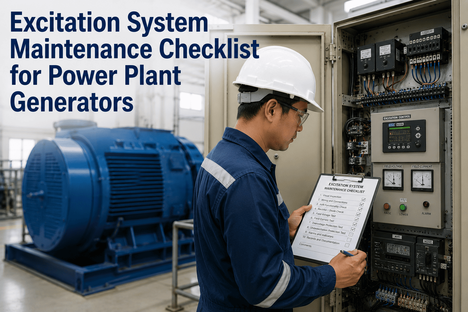
The excitation system is the generator's immune system — when it performs correctly, it is invisible; when it fails, the generator trips, voltage collapse propagates, and grid stability events follow in seconds. Excitation system failures are responsible for approximately 15% of all unplanned generator outages globally, yet most maintenance programs treat excitation equipment with the same inspection cadence as static switchgear, missing the mechanical wear mechanisms that develop in brush gear, slip rings, and rotating diode assemblies long before any protection alarm activates. Both brushed and brushless excitation designs have failure modes that respond only to proactive hands-on inspection, AVR calibration verification, and component trend tracking — none of which can be replaced by DCS monitoring alone. This checklist gives your electrical, protection, and reliability teams a complete inspection framework covering all excitation system types — static, brushless, and AC exciter configurations — structured so every check feeds directly into your OxMaint CMMS preventive maintenance workflow with full calibration records and trend history.
Power Plant · Generator Reliability · Excitation System Checklist
Excitation System Maintenance Checklist for Power Plant Generators
A complete preventive maintenance checklist for static, brushless, and AC exciter systems — covering AVR calibration, brush gear wear, slip ring condition, rotating rectifier health, cooling system integrity, and protection settings — built for generator teams targeting zero excitation-caused outages.
15%
Outages from Excitation Failures
3 Types
Static / Brushless / AC Exciter
IEEE 421.5
Standard for Excitation Models
30 µm
Max Slip Ring Ovality Limit
System Types
Three Excitation System Types — Different Failure Modes, Different Inspection Focus
Maintenance strategy must match the excitation system design. The most common maintenance error is applying a brush-gear-focused checklist to a brushless unit or vice versa — missing the actual failure modes entirely.
Static Excitation
Power electronics on main busbars feed rotor via slip rings and brushes. High initial response speed and precise voltage control — but slip rings and brushes require regular mechanical attention.
Inspection Focus
- Brush length and spring pressure
- Slip ring surface finish and ovality
- Thyristor/diode bridge health
- AVR channel balance and redundancy
Brushless Excitation
Shaft-mounted AC exciter feeds rotating rectifier assembly on the rotor, eliminating slip rings and brushes. Higher reliability in contaminated environments — but rotating rectifier faults are harder to detect without specialist equipment.
Inspection Focus
- Rotating diode and fuse condition
- AC exciter air gap and winding condition
- Field current asymmetry monitoring
- Exciter coupling and alignment
AC Exciter (Separate Shaft)
Separate AC exciter machine on the generator shaft, controlled by AVR via pilot exciter. This configuration is less common in modern units but is still prevalent in older thermal plants and requires both mechanical and electrical inspection routines.
Inspection Focus
- Commutator surface and brush gear
- Pilot exciter winding insulation
- Coupling bolt torque and alignment
- AVR field forcing response test
DDaily
WWeekly
MMonthly
QQuarterly
AAnnual / Outage
Section 1
Daily and Weekly Online Condition Monitoring
These checks can be performed with the generator online and do not require outage access. Consistent daily logging creates the trend baseline that makes abnormality detection reliable — a single reading without historical context has almost no diagnostic value.
Exciter output voltage and field current logged and compared to generator capability curve at current MW and MVAR output — any divergence from the expected field current versus reactive power relationship indicates AVR drift or rotor circuit anomaly
DShift Operator · CMMS performance log
AVR active channel confirmed (CH1 or CH2 as applicable) and standby channel auto-follow verified — standby channel that has drifted from the active channel will cause a voltage transient on channel changeover, disrupting grid supply
DShift Operator · CMMS operator log
Excitation enclosure cooling air flow confirmed — air filter differential pressure below alarm setpoint; cooling fan operation confirmed; inlet and outlet air temperature logged; enclosure temperature above 55°C triggers reliability engineer escalation
DShift Operator · CMMS checklist
For brushed excitation: brush rigging inspection at accessible viewing point — audible confirmation of smooth brush contact, no sparking sounds, no burning smell, and no visible carbon dust accumulation around collector ring area that would indicate abnormal brush wear rate
DShift Operator · CMMS checklist (brushed systems only)
DCS alarm review for excitation system — rotor earth fault relay status, field overcurrent alarms, AVR fault flags, and protection relay status confirmed healthy; any active alarm investigated before shift handover, not carried over unresolved
DShift Engineer · DCS alarm review
Vibration reading from AC exciter bearing positions (where separately mounted) confirmed within baseline ±0.5 mm/s — brushless exciter bearing degradation produces a distinctive increase in the exciter frequency component of the overall vibration spectrum
WReliability Engineer · Vibration trending dashboard
Section 2
Brush Gear and Slip Ring Maintenance Checklist
Brush gear maintenance on static excitation systems is the highest-frequency hands-on task in excitation maintenance. Brushes worn below minimum length lose contact pressure, causing arcing that damages slip ring surface finish — a progressive failure mode that accelerates once it starts.
Check 1
Brush Length
Minimum serviceable length is typically 25–30mm (OEM-specific). Brushes at or below minimum must be replaced immediately — running short brushes causes current concentration, overheating, and slip ring surface scoring.
Check 2
Spring Pressure
Verify spring pressure with calibrated spring gauge — correct pressure ensures uniform current distribution. Both insufficient and excessive pressure cause problems: too low causes arcing; too high causes abnormal ring wear and brush crumbling.
Check 3
Contact Surface
Inspect brush contact face for uneven wear, edge chipping, or glazing. A properly worn brush has a mirror-finish contact face conforming to ring curvature. Glazed or scored contact faces require replacement regardless of remaining length.
Check 4
Brush Holder Clearance
Brush must slide freely in holder without side play exceeding 0.15mm. A stuck brush cannot follow ring surface variations and will lose contact intermittently, causing current spikes. Holder boxes cleaned of carbon dust at each inspection.
All brushes measured and length recorded — brushes at or below minimum replacement length (per OEM data) replaced in sequence maintaining at least 70% of brushes in contact throughout the change-out process to avoid current interruption
MElectrical Technician · CMMS brush change record
Slip ring surface ovality measured with run-out gauge — peak-to-peak ovality must remain below 30 µm; values approaching this limit require ring polishing during next planned shutdown before ovality causes mechanical shock loading on brush gear
QElectrical Technician · CMMS ring measurement log
Slip ring surface finish inspected with magnification — any longitudinal scoring, pitting, or copper transfer from brush material documented with photo in CMMS; surface polishing scheduled if scoring depth exceeds 0.1mm
QElectrical Technician · CMMS ring condition record
Brush holder insulation resistance tested — megger test between each brush holder and earth confirms insulation above 100 MΩ; degraded holder insulation causes partial grounding of the field circuit which activates the rotor earth fault protection
AElectrical Technician · Insulation test certificate
OxMaint tracks every brush replacement, logs slip ring measurements against historical trends, generates AVR calibration due alerts, and maintains a complete excitation system maintenance history — so your team knows the condition of every component before it becomes a generator trip.
Section 3
AVR Calibration and Protection System Verification
An AVR that has drifted from calibration does not trip an alarm — it silently delivers incorrect reactive power dispatch and creates vulnerability to voltage collapse during grid disturbances. Calibration verification must be a scheduled task, not a response to a fault.
AVR voltage setpoint accuracy verified — generator terminal voltage measured with calibrated independent meter and compared to AVR setpoint; deviation greater than 0.5% of rated voltage requires AVR recalibration before next generation period
QProtection Engineer · AVR calibration record
Dual-channel AVR balance confirmed — with unit online, active and standby channel outputs compared; difference greater than 1% requires standby channel trim adjustment to prevent voltage transient on forced or manual channel changeover
MProtection Engineer · Channel balance log
PSS (Power System Stabilizer) gain and phase settings verified against latest system study values — PSS settings that were correct for the grid two years ago may require adjustment following network topology changes or new generation additions in the region
ASystem Protection Engineer · PSS commissioning record comparison
Field forcing ceiling voltage and ceiling current confirmed against generator capability limits — AVR ceiling limiters that have drifted above generator rotor thermal limits create overheat risk during fault recovery voltage forcing events
AProtection Engineer · Limiter verification record
Rotor earth fault relay functional test completed — first-earth-fault detection verified at sensitivity specified in relay settings; second-earth-fault protection trip verified; any sensitivity drift requiring re-calibration documented in CMMS
AProtection Engineer · Relay test certificate
Section 4
Outage Inspection — Brushless and Rotating Rectifier
Brushless excitation rotating components cannot be inspected online. These checks require a planned outage window and are the only opportunity to verify rotating rectifier health before a diode failure causes rotor field asymmetry that may persist undetected through multiple generating periods.
Rotating rectifier assembly removed and all diodes and protective fuses tested — forward and reverse resistance of each diode measured and compared to baseline; any diode showing forward voltage deviation greater than 10% from mean of the group replaced
AElectrical Technician · Rotating rectifier test record
AC exciter rotor and stator winding insulation resistance tested — rotor insulation above 100 MΩ at 500V DC; stator insulation above 1000 MΩ; any measurement below threshold requires drying-out procedure and retest before reassembly
AElectrical Technician · Insulation resistance test log
Exciter coupling condition and alignment checked — coupling bolt torques verified; flexible element condition assessed; shaft alignment between exciter and main generator confirmed within OEM tolerance to prevent vibration-induced bearing and winding fatigue
AMechanical Technician · Alignment record
De-ionised water cooling tubes on rectifier heat sinks inspected and flushed — conductive mineral deposits inside Teflon cooling tubes require full tube replacement if conductivity of flushed water indicates internal contamination; leaking tube connections re-sealed
ACooling Technician · Cooling system inspection record
KPIs
Excitation System Reliability Targets
| Parameter |
Normal Range |
Alert Threshold |
Action Required |
Frequency |
| Brush Length |
Above minimum OEM length |
At minimum replacement length |
Replace immediately |
Monthly |
| Slip Ring Ovality |
Below 15 µm |
Above 25 µm |
Schedule ring polishing |
Quarterly |
| AVR Voltage Accuracy |
Within ±0.3% of setpoint |
Deviation above 0.5% |
Recalibrate AVR |
Quarterly |
| Enclosure Temperature |
Below 45°C |
Above 55°C |
Check cooling system |
Daily |
| Rotor Insulation Resistance |
Above 1000 MΩ (cold) |
Below 100 MΩ |
Dry-out and retest |
Annual/Outage |
| Excitation-Caused Outages |
Zero per year |
Any single event |
Full RCA and schedule review |
Per event |
FAQs
Frequently Asked Questions
What is the most common cause of excitation system failures in power plants?
In brushed static excitation systems, worn brushes and deteriorating slip ring surface finish are the leading causes of unplanned excitation trips. In brushless systems, rotating diode failure — often from voltage transients — is the most frequent cause. In both cases, failures are preventable with regular scheduled inspection and trend monitoring rather than responding only after alarm activation. OxMaint tracks excitation component wear trends automatically.
How often should AVR calibration be verified?
AVR voltage accuracy should be verified quarterly with an independent calibrated reference meter, and standby channel balance should be checked monthly. Annual outage inspection is the window for full protection setting verification and field forcing limiter checks. AVR drift is gradual and silent — it does not produce alarms until the deviation is already affecting reactive power dispatch.
Can brushless excitation systems develop faults that are not detected by online monitoring?
Yes. Partial rotating rectifier failures — such as a single diode going high-resistance rather than open-circuit — can persist for months with no DCS alarm. The generator continues producing rated output, but field current asymmetry causes progressive rotor winding hotspot development. Detection requires periodic outage-based rotating rectifier testing, which cannot be replaced by any online monitoring signal. Book a demo to see how OxMaint schedules excitation outage inspections.
What is the correct approach to brush replacement to avoid field current interruption?
Replace brushes sequentially, never removing more than one brush per ring at a time and allowing each new brush to seat for at least 15 minutes before removing the next. Maintain at least 70% of brushes in contact during the entire change-out sequence. New brushes must be pre-shaped to ring curvature before installation — flat-faced new brushes installed without seating cause sparking and ring damage during the bedding-in period.
What CMMS features are most valuable for excitation system maintenance management?
The highest-value features are component-level trend tracking (brush length, slip ring ovality, AVR accuracy over time), automatic calibration due date alerts, outage-linked inspection scheduling for rotating rectifier access, and digital storage of test certificates for protection relay and insulation tests. A CMMS that cannot trend numeric measurements has limited value for excitation system management compared to one designed for asset-level parameter history. Start your OxMaint free trial and configure excitation system templates in minutes.
Ready to Deploy This Checklist?
Every Brush Measured. Every AVR Calibrated. Every Generator Running.
OxMaint manages your complete excitation system maintenance program — scheduling daily online checks, monthly brush inspections, quarterly AVR calibration verifications, and annual outage-based rotating rectifier tests in a single platform with full trend history, digital test certificates, and automatic alerts when any parameter drifts toward an actionable threshold.