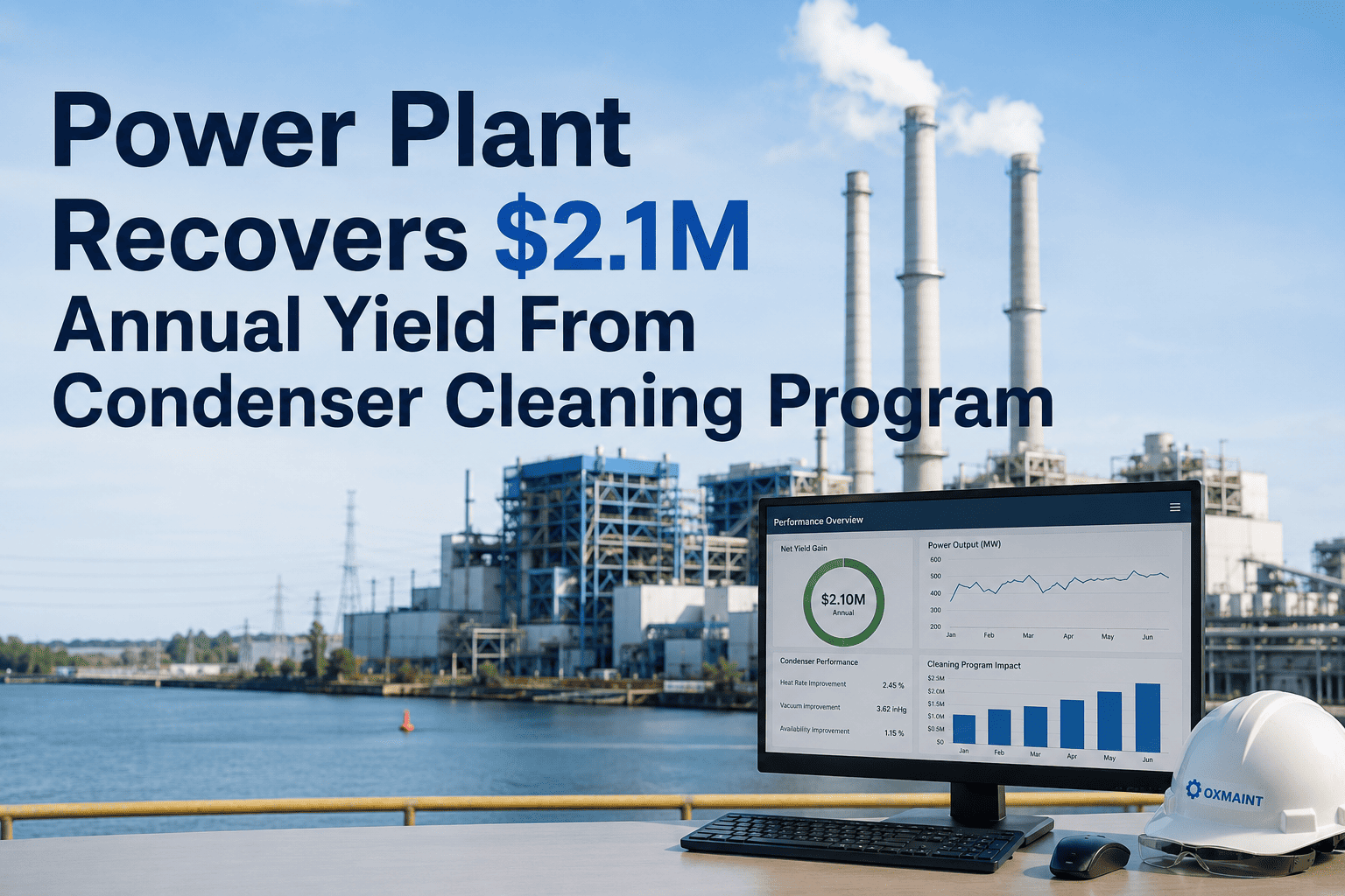
Condenser tube fouling, backpressure losses, and undetected wall thinning cost power plants millions in heat rate penalties and forced outages every year. Sign Up Free on OxMaint to schedule, track, and document every condenser cleaning campaign and eddy current inspection in one CMMS — with automatic work order generation tied to backpressure thresholds and time-based PM triggers.
Why Condenser Performance Drives Plant Economics
The steam surface condenser is the cold end of the Rankine cycle — and its cleanliness factor directly dictates turbine backpressure, heat rate, and net output. A condenser operating at design cleanliness (typically 85%) delivers rated backpressure. Every percentage point of fouling beyond design adds measurable backpressure, reducing turbine output and increasing fuel consumption per MWh generated.
The Four Fouling Mechanisms You Must Track Separately
Effective condenser maintenance begins with correctly diagnosing the fouling mechanism. Different fouling types respond to different cleaning methods and occur at different rates — treating them as a single problem leads to incorrect cleaning intervals and persistent performance degradation.
Algae, barnacles, mussels, and biofilm attach to tube inner walls in once-through cooling systems drawing from rivers, lakes, or seawater. Growth rate is temperature and season-dependent — accelerating in summer months and warmer intakes. Requires chlorination programs, mechanical brushing, or high-pressure hydroblasting to remove without tube damage.
Suspended solids in cooling water settle inside low-velocity tubes or water boxes, reducing flow area and thermal conductivity. Common in river-fed systems during flood events or high-turbidity seasons. Requires increased cleaning frequency during seasonal silt peaks and may indicate intake screen maintenance deficiencies.
Calcium carbonate, magnesium silicate, and other mineral salts precipitate out of solution as cooling water is concentrated in recirculating tower systems. Scale forms a hard, thermally resistive layer that cannot be removed by mechanical means alone — requiring chemical descaling (acid wash) or EDTA-based cleaning solutions during outage.
Iron oxides, copper compounds, and corrosion products from upstream piping deposit on tube walls in both carbon steel and copper alloy tube bundles. Corrosion fouling is often self-accelerating — the deposit creates differential aeration cells that accelerate pitting. Tracking via eddy current over multiple outage cycles is the only way to distinguish corrosion-caused wall loss from manufacturing variation.
Cleaning Method Selection Matrix
Selecting the wrong cleaning method damages tube walls, shortens service life, and increases eddy current reject rates at the next inspection. The following matrix maps fouling type to validated cleaning method and important application constraints.
| Fouling Type | Recommended Method | Operating Mode | Key Constraint | Typical Duration |
|---|---|---|---|---|
| Biological (soft) | Automatic ball cleaning system (ABCS) | Online | Ball diameter must match tube ID; requires ball collector screens | Continuous |
| Biological (hard-attached) | High-pressure hydroblasting (1,000–3,000 psi) | Offline | Pressure selection by tube material — lower pressure for thin-wall titanium | 5–7 days |
| Particulate / Silt | Mechanical brushing or low-pressure water flush | Offline | Verify brush size — oversized brushes abrade tube ID and increase ECT defect rate | 2–4 days |
| Mineral Scale (hard) | Chemical acid wash (HCl or citric acid) | Offline | Inhibitor required to prevent base metal attack; pH monitoring during wash | 3–5 days |
| Corrosion Products | EDTA chelant cleaning + mechanical finishing | Offline | Waste disposal permits required for chelant solutions in most jurisdictions | 4–6 days |
Eddy Current Testing: Program Structure and Tube Plugging Decisions
Eddy current testing (ECT) is the industry standard NDE method for assessing condenser tube wall condition — detecting wall thinning, pitting, erosion, and cracks that are invisible on the outer surface. A well-structured ECT program turns inspection data into RUL (remaining useful life) estimates and plugging decisions that prevent forced outages.
On first ECT campaign (new plant or post-retube), test 100% of tubes to establish baseline wall thickness distribution across the full bundle. This baseline is the reference against which all future rate-of-change calculations are made. Without it, RUL estimation is impossible.
After baseline, focus subsequent campaigns on statistically sampled zones plus 100% testing in historically high-defect areas (inlet and outlet tubesheet rows, support plate contact zones, and air removal zones). Typical sample rates: 20–25% per campaign in low-risk zones, 100% in elevated-risk zones.
ECT signals are graded by wall loss percentage. Industry standard plugging thresholds: plug at 80% wall loss (immediate), monitor at 60–79% (retest next outage), accept at below 60%. Grading must be performed by Level II or Level III ECT technicians per ASNT SNT-TC-1A — not by cleaning crews using simplified screening probes.
For tubes in the monitor category, calculate rate-of-wall-loss per year from successive ECT campaigns. Extrapolate to predict when each tube will cross the plugging threshold. CMMS integration allows plotting defect population trends across outage cycles — identifying accelerating degradation before it drives up the emergency plug rate.
Plug all tubes meeting or exceeding the threshold using titanium or stainless expansion plugs — document tube row, column, and shell position in CMMS against the asset record. When cumulative plug rate exceeds 10–15% of total tube count, initiate retube or tube insert feasibility analysis. This threshold varies by condenser design and thermal margin.
CMMS Records Required for Condenser Programs
Condenser maintenance decisions — cleaning frequency, ECT sample rate, plug threshold, retube timing — are only as good as the historical data behind them. Every activity must generate a closed work order tied to the condenser asset record in CMMS.
| Record Type | Required Data Fields | Retention Period |
|---|---|---|
| Cleaning Campaign WO | Method, pressure, duration, cleanliness factor before/after, backpressure delta, crew, date | Plant life |
| ECT Inspection Report | Probe type, technician qualification, sample rate, defect map, plug list, date | Plant life |
| Tube Plug Record | Shell ID, row/column position, wall loss %, plug type, installer, date | Plant life |
| Backpressure Log | Date, load, CW inlet temp, measured backpressure, design backpressure, cleanliness factor calculated | 5 years minimum |
| Water Chemistry Log | LSI, cycles of concentration, biocide dosing, corrosion inhibitor ppm, pH | 3 years minimum |
Expert Review
The single biggest condenser program mistake I see is running ECT without a proper baseline. You get a defect population at inspection but you cannot tell if a 35% wall loss tube is getting worse or has been stable for 10 years. Invest in 100% baseline testing on year one — the data pays for itself in the second outage when you can confidently defer plugging decisions on stable tubes.
Backpressure-triggered cleaning campaigns consistently outperform calendar-based programs in both cost and performance outcomes. A plant cleaning every 6 months regardless of fouling rate is either cleaning too early (wasting outage time) or too late (absorbing heat rate penalties). The data to do this right exists in your DCS — you just need the CMMS structure to act on it systematically.