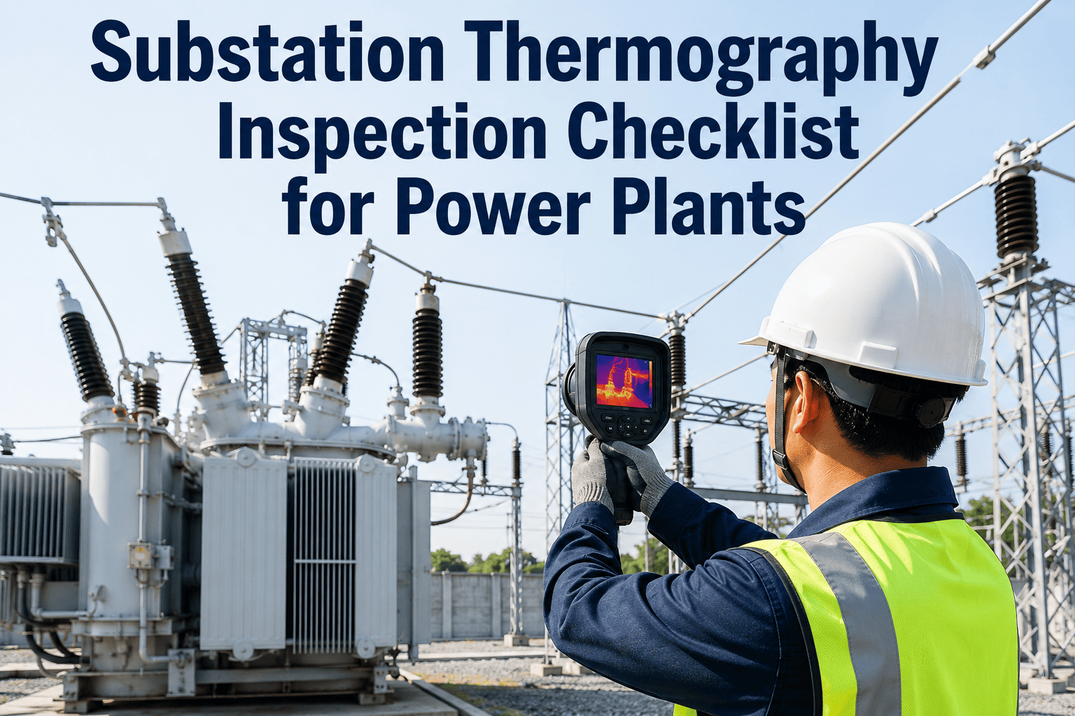
Substation equipment failures from undetected thermal anomalies cost power plants millions in emergency repairs, unplanned outages, and safety incidents every year. Infrared thermography is the gold standard for identifying overheating bus bars, loose connections, failing transformers, and degraded switchgear — but only when performed systematically, on schedule, and with findings logged to a digital work order system. OxMaint's Inspection Management platform digitises your entire substation thermography programme — from route planning and camera calibration through defect classification, work order generation, and regulatory reporting. Book a free demo and see how power plants cut thermal fault response time by 60%.
Checklist · Power Plants · Substation Thermography · Inspection Management
Substation Thermography Inspection Checklist for Power Plants
A complete field-to-work-order thermography checklist covering pre-inspection setup, camera calibration, zone-by-zone scanning, defect classification, and corrective action workflows — built for power generation substations.
73%
of electrical failures in substations are preceded by detectable thermal anomalies
6x
higher repair cost when thermal faults are discovered after failure vs. during thermography
IEC 60076
and NFPA 70B require documented thermal inspection records for substation assets
Quarterly
minimum inspection frequency recommended for high-load power plant substations
Why Thermography Programmes Fail Without Digital Inspection Management
No calibration records
Camera emissivity settings and ambient compensation values not documented — temperature readings are meaningless without verified calibration at time of scan.
Incomplete zone coverage
Inspectors skip difficult-access panels or time-constrained zones. No checklist enforcement means gaps go undetected until a fault triggers an outage.
Findings not linked to assets
Thermal images saved to a local hard drive rather than linked to the specific asset in the CMMS — history is lost when the technician leaves.
Delayed work order creation
Defects found in the field are reported days later in a spreadsheet. Corrective work is not planned, prioritised, or tracked against the thermal finding.
No trend comparison
Without a digital record per asset per inspection cycle, temperature rise trends across quarters are invisible — the early warning function of thermography is lost.
Audit exposure
Insurance and regulatory audits require documented thermography records by zone and asset. Paper logs and scattered image files do not meet this standard.
Pre-Inspection Setup Checklist
Before the camera enters the substation yard, every setup item must be confirmed. Incorrect emissivity settings or uncalibrated equipment produce readings that appear normal on a faulty component — the most dangerous outcome in thermography.
Phase 1
Pre-Inspection Setup and Equipment Verification
Thermal camera NIST calibration certificate current
Verify calibration certificate date against plant calibration schedule. Camera must have been calibrated within the interval specified by the OEM and plant QA procedure. Do not use out-of-calibration equipment.
Emissivity values set per material type for each substation zone
Emissivity values configured in camera for oxide copper bus bars, painted steel enclosures, and bare aluminium conductors as applicable per zone. Incorrect emissivity produces systematically wrong temperature readings.
Ambient temperature and reflected temperature compensations entered
Ambient temperature recorded at inspection start. Reflected apparent temperature measured using a crumpled aluminium foil reflector per ASTM E1862. Both values entered into camera firmware compensation fields before scanning begins.
Load conditions at minimum 40% rated capacity confirmed
Thermal inspection is only valid above minimum load threshold. Confirm substation load is at or above 40% of rated capacity with the control room before beginning — note the actual load percentage in the inspection record.
PPE and safe approach distance confirmed per NFPA 70E arc flash boundary
Arc flash boundary distances confirmed from the most recent arc flash study for each panel and switchgear bay. PPE category confirmed and worn. Inspection route approved by the substation safety officer before entry.
Inspection route and zone sequence loaded in OxMaint mobile app
Digital inspection route loaded with all asset IDs, access panel sequences, and minimum dwell times per zone. Route confirmed to cover every panel, transformer bay, and cable tray section per the substation inspection register.
Zone-by-Zone Scanning Checklist
The scanning sequence matters. Start at the highest-voltage equipment, work to lower voltage zones, and scan each component from the same angle and distance used in the previous inspection cycle to ensure valid trend comparison.
| Substation Zone | Key Components to Scan | Critical Temperature Delta | Work Order Trigger |
|---|---|---|---|
| HV Bus and Gantry | Bus bar joints, clamps, strain insulators, jumper connections | ΔT > 10°C vs. similar phase | Immediate isolation planning |
| Power Transformers | Bushing tops, HV/LV terminals, tap changer, OLTC contacts | ΔT > 8°C above ambient or phase imbalance | Schedule outage within 30 days |
| Switchgear / Circuit Breakers | Breaker contacts, bus connections, control cable terminals | ΔT > 15°C vs. reference | Priority PM work order |
| LV Panels / MCCs | Incomer terminals, busbar risers, fuse connections, cable lugs | ΔT > 20°C vs. ambient | Corrective work within 7 days |
| Battery Chargers and UPS | Rectifier terminals, DC bus bars, fuse carriers, contactors | ΔT > 10°C above ambient | Corrective WO within 14 days |
| Cable Trays and Ducts | Cable splices, penetration seals, tray fill hotspots, conduit ends | ΔT > 12°C above adjacent cable | Inspect and de-rate or replace |
| Capacitor Banks | Capacitor unit tops, fuse connections, disconnect switches | Any unit > 5°C hotter than bank average | Replace unit and test bank |
Phase 2
Field Scanning — Asset-by-Asset Confirmation
Each asset scanned and tagged with asset ID in digital inspection form
Every component scanned is linked to its unique asset ID in OxMaint before moving to the next component. No scan is recorded as a standalone image — each finding is immediately tied to the asset record for trend tracking.
Thermal and visual image pair captured for every component
Both a thermal image and a visible-light photo captured at each scan point. The image pair enables reviewers to precisely locate the thermal anomaly within the physical equipment — thermal only is insufficient for work order scope definition.
Max temperature, hot spot location, and phase comparison recorded per component
Maximum temperature recorded at hotspot. If multi-phase equipment, temperature of all three phases recorded and delta calculated. Phase imbalance is often more significant than absolute temperature as a fault indicator.
Anomaly severity classified per IEC 60076 temperature rise criteria
Each anomaly classified as Normal, Advisory, Actionable, or Critical using the plant's defined temperature delta thresholds. Classification drives automatic work order priority in OxMaint — Critical findings trigger same-day notification to the plant manager.
All panels opened per safe work procedure — no closed-door thermal scanning
Every panel requiring internal scan opened per the plant's energised electrical work permit procedure. Closed-door scanning through ventilation slots is not permitted as a substitute for direct view — findings from closed-door scans must be flagged as unconfirmed.
Comparison with previous inspection cycle temperature values confirmed
Previous cycle temperature values for this asset retrieved from OxMaint asset history. Current readings compared against prior values. Any rise of more than 5°C since the last inspection is flagged for trend review regardless of whether it crosses the action threshold.
Close the gap between thermal findings and corrective work orders
OxMaint links every thermal anomaly directly to a prioritised work order — with the image pair, asset history, and defect classification attached. No finding is lost between field inspection and the maintenance schedule.
Defect Classification and Work Order Generation
Normal
ΔT < 5°C
Log and close. No corrective action required. Include in next scheduled inspection cycle.
Advisory
ΔT 5–10°C
Schedule inspection and cleaning within 90 days. Monitor at next quarterly thermography cycle.
Actionable
ΔT 10–20°C
Corrective work order raised within 7–30 days. Schedule tightening, cleaning, or component replacement at next available outage window.
Critical
ΔT > 20°C
Immediate isolation planning. Emergency work order raised. Plant manager and reliability engineer notified same shift. No deferral without written risk acceptance.
Phase 3
Post-Inspection — Reporting, Work Orders, and Closure
Thermography inspection report generated with full asset-level findings
OxMaint generates the full inspection report from the digital checklist data — including zone coverage summary, total anomalies by severity class, thermal image pairs, and work order numbers raised. Report attached to the substation asset record.
Corrective work orders created and assigned with completion deadline
Every Actionable or Critical finding has a work order created, assigned to a qualified technician, and given a completion deadline consistent with the severity classification. Work order includes the thermal image, asset location, and defect description from the inspection form.
Verification re-scan scheduled for corrected components
Re-scan inspection scheduled in OxMaint within 30 days of corrective work completion. Re-scan verifies that the temperature delta has returned to Normal range. Without verification re-scan, the finding remains open in the asset history.
Inspection records filed for regulatory and insurance audit
Complete inspection record — checklist completion, image pairs, severity classifications, work orders raised, and re-scan results — stored in OxMaint's searchable audit log. Accessible for NFPA 70B, IEC 60076, and insurance underwriter reviews without manual document retrieval.
Key Performance Indicators — Substation Thermography Programme
Zone Coverage Rate
Percentage of substation zones scanned vs. total zones on the inspection register. Target 100% per inspection cycle — any missed zone is a compliance and reliability gap.
Anomaly Detection Rate
Number of Actionable or Critical findings per 100 components scanned. A rising rate signals ageing connections; a sudden drop may indicate calibration or procedure problems.
Work Order Closure Within SLA
Percentage of corrective work orders completed within the deadline set by their severity classification. Below 90% indicates resource or planning gaps in the corrective maintenance workflow.
Verification Re-Scan Completion
Percentage of corrected components that have received a verification re-scan within 30 days of work order closure. Confirms the corrective action resolved the thermal anomaly.
Digitise Your Substation Thermography Programme with OxMaint
OxMaint's Inspection Management platform gives power plant teams a fully digital thermography checklist — calibration records, zone-by-zone scanning, automated defect classification, instant work order generation, and audit-ready reports — all linked to each substation asset for full lifecycle thermal history.
Frequently Asked Questions
What equipment should a power plant substation thermography checklist cover?
A comprehensive substation thermography checklist should cover HV bus bars and gantry connections, power transformers including bushing tops and OLTC contacts, all circuit breaker and switchgear bays, LV panels and motor control centres, battery chargers and UPS systems, cable trays and splice points, and capacitor banks. Each component type has its own temperature delta threshold for defect classification. OxMaint's digital inspection route ensures every zone is covered on every inspection cycle, with no components skipped due to time pressure or access difficulty. Configure your substation thermography route in OxMaint — free 14-day trial.
What load conditions are required for valid substation thermography?
Thermography produces valid results only when the substation is under meaningful electrical load. The widely accepted minimum threshold is 40% of rated capacity, though many plant procedures require 60–80% for high-value transformer inspections. Below the minimum load threshold, resistive heating in connections is insufficient to produce detectable temperature differentials — genuine faults will not show. The load level at inspection start must be recorded as part of the inspection record, as it affects the interpretation of all temperature readings taken during that session. OxMaint prompts technicians to confirm and log load conditions before the digital checklist allows scanning to proceed.
How does OxMaint connect thermography findings to corrective work orders?
When an inspector classifies a thermal anomaly as Actionable or Critical in the OxMaint mobile inspection form, the platform automatically creates a corrective work order with the thermal and visual image pair attached, the asset ID, defect classification, severity, and the recommended completion deadline pre-populated from the classification rules. The work order is routed to the assigned technician and tracked through completion. A verification re-scan task is then scheduled to close the loop. Every step — inspection finding, work order, completion, and re-scan — is linked to the substation asset record for full audit traceability. Book a demo to see the end-to-end thermography workflow.
How often should power plant substations undergo thermography inspection?
NFPA 70B recommends thermography inspection of critical electrical equipment at least annually, with quarterly inspections for high-load or aged substations. Many power generation plants operating under reliability centred maintenance frameworks perform thermography quarterly on transmission and generation-side substations and semi-annually on auxiliary power systems. Following any major change — new connection, equipment replacement, or fault event — a targeted re-inspection should be performed within 30 days regardless of the scheduled cycle. OxMaint tracks inspection intervals per substation zone and alerts the maintenance team when an inspection is due or overdue.
What records does the checklist generate for regulatory and insurance compliance?
Each completed OxMaint substation thermography inspection generates a full digital record including: inspection date, inspector ID, camera calibration certificate reference, ambient and reflected temperature values, load conditions at time of inspection, zone-by-zone scan coverage confirmation, per-asset temperature readings and severity classifications, thermal and visible image pairs, corrective work order numbers with target completion dates, and verification re-scan results. This record set satisfies NFPA 70B documentation requirements and meets the evidence standards required by most power plant insurance underwriters for premium maintenance on electrical systems. Records are searchable and exportable for audit at any time.