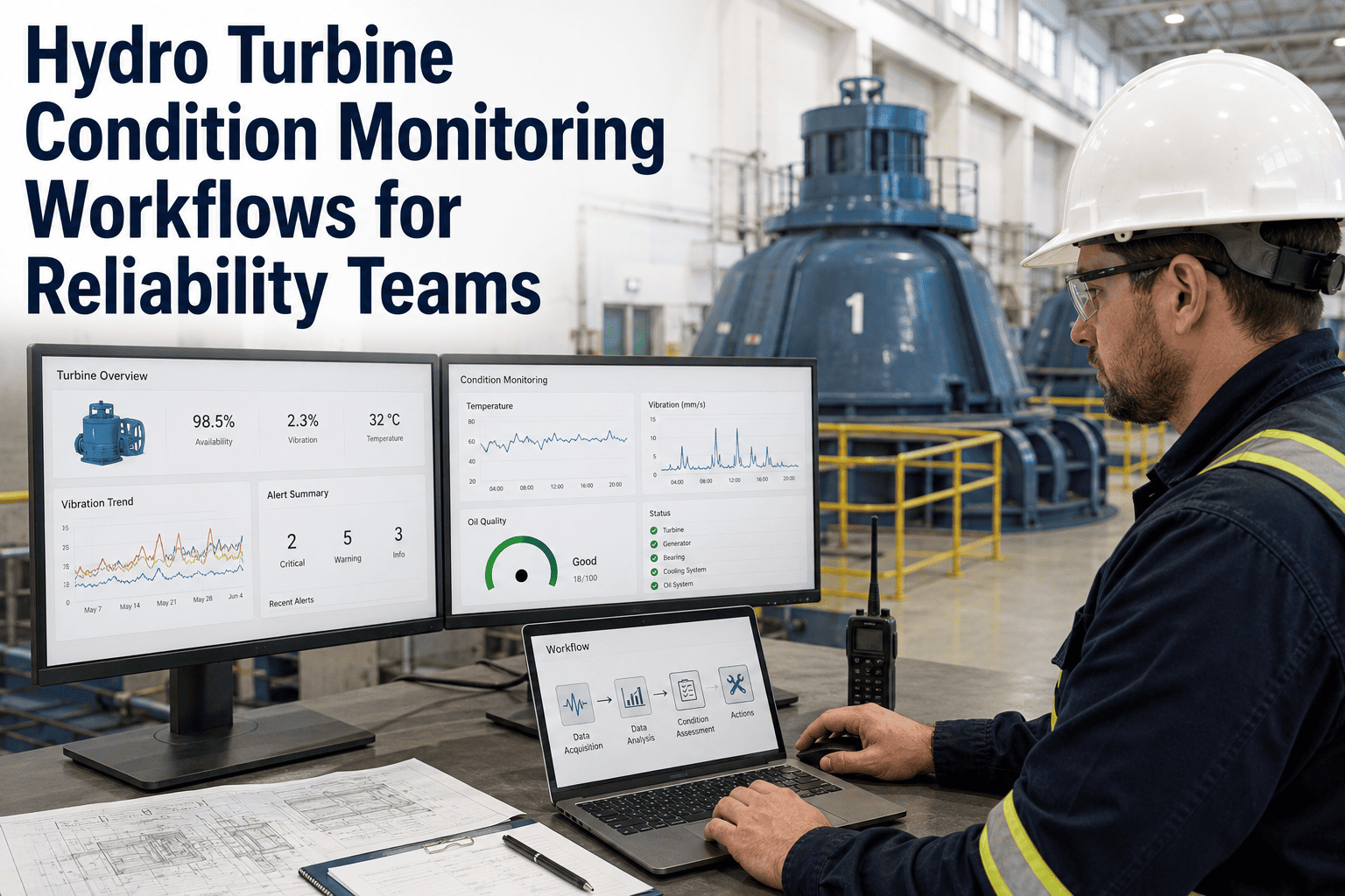
A hydro turbine running with advancing cavitation erosion, a widening runner blade pit, or a rising shaft vibration trend is losing both efficiency and residual life — and unless your reliability team has a structured workflow connecting sensor data, pit depth measurements, and efficiency curves into a single asset record, none of those deterioration signals will reach a planned repair decision before the damage requires a blade replacement or an emergency outage. The gap between raw condition data and a maintenance action is where most hydro O&M programs lose money. OxMaint's condition monitoring workflows close that gap — connecting acoustic emission readings, vibration trends, and efficiency deviation data into structured work orders with remaining useful life estimates that give reliability engineers lead time, not incident reports.
The 4 Condition Domains Every Hydro Reliability Team Must Monitor
Hydro turbine condition monitoring is not a single-sensor exercise. Runner degradation, bearing health, shaft alignment, and hydraulic efficiency each fail on their own timeline and through their own signal — and they interact. A runner developing cavitation erosion changes its vibration signature, reduces hydraulic efficiency, and ultimately changes bearing load distribution. Reliability teams need workflows that track all four domains together.
See Condition Monitoring Workflows Running on Your Turbines
OxMaint connects vibration, cavitation, bearing, and efficiency data into structured workflows — giving your reliability team lead time, repair windows, and financial evidence instead of reactive incident response.
Workflow: From Condition Signal to Planned Repair
Condition Monitoring by Turbine Type
Frequently Asked Questions
How does OxMaint connect sensor data to condition monitoring workflows without replacing existing SCADA?
OxMaint integrates with plant SCADA via OPC-UA, Modbus, and REST API — ingesting vibration, temperature, pressure, and acoustic signals alongside your existing SCADA display. Sensor data flows into OxMaint's condition monitoring engine while SCADA continues its normal control function. No hardware replacement, no SCADA reconfiguration. Start a free trial to see data flowing from your existing instrumentation into OxMaint condition workflows within days.
How are cavitation pit depth measurements tracked across multiple inspection cycles?
Each runner is divided into measurement zones defined in the initial OxMaint setup — matching the zones in your existing inspection protocol. Field technicians enter pit depth per zone per inspection using the mobile app, and OxMaint calculates the zone-by-zone deterioration rate across inspection cycles automatically. When any zone's rate indicates the damage will reach the weld repair threshold before the next scheduled outage, the system generates an alert and updates the repair planning timeline. Book a demo to see this workflow on a Francis runner.
Can reliability teams access turbine condition data remotely across multiple sites?
Yes. OxMaint provides a portfolio-level reliability dashboard accessible from any browser or mobile device — showing condition status per unit, active anomaly count, open finding age, and PM completion rate across all sites simultaneously. Reliability engineers at a central office can monitor all units and drill to individual sensor trend charts without visiting the plant.
How does OxMaint quantify the revenue impact of efficiency degradation on a hydro unit?
OxMaint compares actual unit output against the expected output at the same measured head and flow conditions using the turbine's design hill curve as the reference. The efficiency deviation is multiplied by the operating hours and local energy value to produce a monthly revenue impact figure. When efficiency degradation accumulates past a defined threshold, the system generates a financial case for repair authorization — turning a percent efficiency loss into a dollar amount that engineering and finance can both act on.
What is the typical lead time OxMaint delivers before a bearing failure on a hydro turbine?
Most hydro guide bearing faults are detectable 12–18 days before functional failure using vibration spectrum analysis at bearing fault frequencies. OxMaint monitors these frequencies continuously and confirms bearing anomalies when vibration, temperature, and oil analysis signals deviate simultaneously in the bearing failure pattern. At a large hydro facility managing multiple Francis units, AI monitoring can detect 10 or more developing bearing faults per year — each representing a planned bearing replacement at a fraction of the cost of an emergency outage.
Build Condition Monitoring Workflows Your Reliability Team Will Actually Use
OxMaint connects sensor data to planned repairs — not just dashboards. Most hydro reliability teams are fully operational in OxMaint within 3 weeks of deployment.