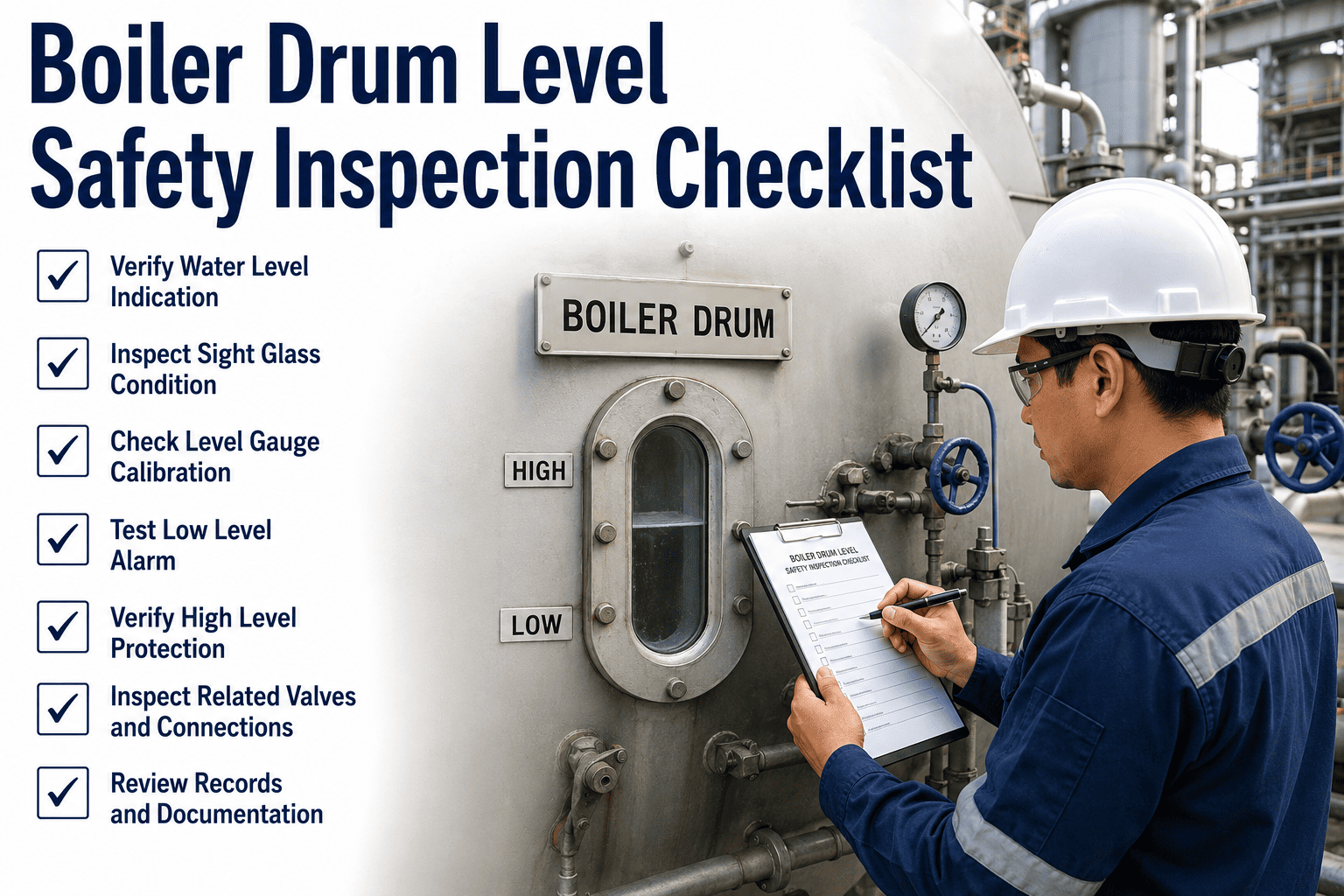
Boiler drum level is the most consequential measurement in a steam power plant — a high-level trip floods the steam lines and damages turbine blades, while a low-level trip starves the boiler of water and can cause catastrophic tube failure within minutes. Despite being the single most critical process variable in thermal power generation, drum level instrumentation systems are routinely found with blocked gauge glass cocks, drifted transmitter zero references, and mismatched readings between redundant instruments that nobody has investigated. OxMaint's Inspection Management platform digitises your boiler drum level inspection programme — routing every gauge calibration, level switch test, and transmitter verification through a structured digital checklist with automatic work orders for any deviation found. Book a demo to see how power plants eliminate drum level instrumentation failures with OxMaint.
Checklist · Power Plants · Boiler Safety · Inspection Management
Boiler Drum Level Safety Inspection Checklist for Power Plants
A comprehensive drum level safety inspection checklist covering gauge glass verification, transmitter calibration, level switch testing, high/low trip system confirmation, and feedwater control loop validation — structured for ASME Section I compliance and power plant reliability.
What Drum Level Failures Actually Cost
High Level Trip
Steam drum priming — moisture carryover into steam lines
Turbine blade erosion, steam line water hammer, control valve seat damage
Typical repair: $250,000–$2M depending on turbine stage affected
Low Level Trip
Boiler tube starvation — uncovered tubes overheat under heat flux
Tube rupture, tube sheet cracking, refractory damage, forced outage
Typical repair: $500,000–$5M plus 4–12 weeks of forced outage
Instrumentation Failure (No Trip)
Plant operates without valid drum level — next upset has no protection
Loss of safety function — requires immediate load reduction or shutdown per ASME Section I
Cost of undetected instrument failure: potentially the entire boiler
A
Gauge Glass (Direct Level Indication)
The primary visual reference for operators. Magnetic level gauges and flat glass gauges both require regular blow-down to prevent false readings from blocked isolating cocks or sediment accumulation in the gauge body. Colour-coded magnetic float positions must match drum transmitter readings.
Inspection: Daily blow-down verification; monthly calibration check vs. transmitters
B
Differential Pressure (DP) Transmitters
Typically three independent DP transmitters per drum for 2-out-of-3 trip voting logic. Each has its own impulse lines, condensate pots, and zero calibration reference. Blocked impulse lines are the most common cause of transmitter drift — and produce a false reading in the safe direction, masking the real level.
Inspection: Weekly cross-check between transmitters; quarterly zero and span calibration
C
Level Switches (High/Low Trip)
Discrete switches that trigger the high and low level boiler trips. Most plants use float-type or displacer-type level switches on separate nozzles from the transmitters. Each switch must be trip-tested to confirm the relay output reaches the protection system — visual inspection of the switch float alone is insufficient.
Inspection: Monthly trip test; annual bench calibration
D
Three-Element Feedwater Control
The feedwater control loop uses drum level, steam flow, and feedwater flow to maintain level within the normal control band. A drifted drum level transmitter input to the controller produces steady-state level error without alarming — plants think level is normal when the true level is 50–100mm above or below the displayed value.
Inspection: Daily controller deviation check; monthly loop calibration verification
Daily
Per-Shift Drum Level Instrumentation Verification
Gauge glass blow-down completed — both isolating cocks confirmed open after blow-down
Gauge glass blow-down procedure completed per the plant operating procedure. Both the steam cock and water cock confirmed open after blow-down. Level observed to return promptly after drain cock is closed — a slow return or erratic level movement indicates a partially blocked cock requiring work order. Gauge glass reading recorded at steady state.
Three DP transmitter readings cross-checked — deviation between any two transmitters below 25mm
Level readings from all three DP transmitters recorded simultaneously and compared. Deviation greater than 25mm between any two transmitters must be investigated before the shift continues. If two transmitters agree and one diverges, the divergent transmitter is likely blocked — isolate it from the voting logic and raise a work order for impulse line inspection and clearing.
DP transmitter readings cross-checked against gauge glass — deviation below 30mm
Average of the valid DP transmitter readings compared against the gauge glass reading. DP transmitters indicate density-compensated level while the gauge glass shows true water column height — a small offset is expected, but deviation above 30mm indicates either a transmitter calibration drift or a gauge glass reading error requiring investigation before the next shift.
DCS drum level controller deviation alarm checked — no sustained offset from setpoint
Three-element feedwater controller output and deviation alarm reviewed on DCS. A sustained deviation (controller maintaining level more than 50mm from setpoint for over 15 minutes at steady load) indicates a calibration drift in one of the three control loop inputs. Trend the deviation against load changes to identify whether it is the drum level, steam flow, or feedwater flow element causing the offset.
High and low level alarm setpoints confirmed active in DCS — no bypasses in effect
DCS alarm summary reviewed for drum level. High level alarm, low level alarm, high-high trip, and low-low trip setpoints confirmed active and not bypassed. Any active bypass must have an approved bypass record in OxMaint with an expiry time. Bypasses in effect at shift start without a valid record are treated as uninvestigated instrumentation faults.
Monthly
Level Switch and Trip System Function Test
High level switch (LAHH) trip-tested — relay output confirmed at protection system terminal
High-high level switch test initiated per the plant's safety instrumented system test procedure. Switch float or displacer lifted to simulate high level condition. Relay output confirmed at the protection system input terminal — not just at the switch itself. Trip logic response confirmed (boiler feed pump runback or turbine trip as designed). All actions logged in OxMaint against the trip system asset ID.
Low level switch (LALL) trip-tested — relay output confirmed at protection system terminal
Low-low level switch test initiated. Switch float lowered to simulate low level condition. Relay output confirmed at the boiler trip / burner management system input. Response confirmed per the trip logic description. Any switch that fails to change state, fails to reach the protection system, or produces an incorrect logic response is tagged out and an emergency work order raised — no operation without a valid low level trip.
Voting logic verified — 2-out-of-3 response confirmed for DP transmitter trips
Protection system voting logic tested by simulating the trip condition on each individual transmitter in turn, confirming that no single transmitter alone trips the unit (avoids spurious trips), then simulating two transmitters simultaneously to confirm the 2oo3 trip fires correctly. Logic controller response record printed and filed in OxMaint against the protection system monthly test record.
Impulse lines blown down and condensate pots confirmed full
Transmitter impulse lines blown down per the maintenance procedure to clear any sediment or partial blockage. Condensate pots on high-pressure DP transmitters refilled to the reference level before the transmitter is returned to service. Transmitter reading after blow-down and refill confirmed within 10mm of the gauge glass reading — any greater offset after this procedure indicates a transmitter zero calibration error.
Eliminate drum level instrumentation gaps before they cause a boiler trip or tube failure
OxMaint schedules daily cross-checks, monthly trip tests, and quarterly calibrations for every drum level instrument automatically — generating work orders for deviations and maintaining the protection system test record required by ASME Section I and insurance inspectors.
Quarterly
DP Transmitter Zero and Span Calibration — Off-Load or On-Load
DP transmitter zero reference confirmed at cold condensate pot reference conditions
Transmitter isolated from process, zero pressure applied across both legs. Zero output confirmed within ±2mm water column equivalent. Zero error outside this tolerance adjusted per the transmitter calibration procedure. Zero shift is the most common DP drum level error — condensate pot temperature changes with ambient conditions and causes systematic zero drift between annual calibrations if not periodically verified.
Span calibration verified — transmitter output confirmed at 25%, 50%, 75%, and 100% of measurement range
Calibrated pressure source applied at four points across the transmitter measurement range. Output at each point recorded and compared against the theoretical value. Any deviation greater than ±5mm at any calibration point requires transmitter adjustment. Calibration certificate generated in OxMaint and stored against the instrument ID.
Trip setpoints verified at protection system — confirmed unchanged from approved values
High-high and low-low trip setpoints in the protection system verified against the plant's approved safety case setpoint register. Any setpoint found to have drifted or been modified without a management of change record triggers immediate escalation. Setpoint verification results recorded in OxMaint with authorising engineer sign-off.
Feedwater control valve position and controller tuning verified at normal operating load
Feedwater control valve(s) confirmed responding correctly to level demand from the three-element controller. No valve hunting, stiction, or saturated controller output observed at normal load. Controller integral windup limits confirmed configured correctly. Any feedwater control valve with hysteresis above 2% of stroke or a stuck-at-limit output condition flagged for maintenance during the next available outage window.
Daily Cross-Check Completion Rate
Percentage of shifts where the gauge glass vs. transmitter cross-check and three-transmitter comparison were completed and logged. Target 100% — any missed shift is a compliance gap and a reliability risk.
Transmitter Deviation Frequency
Number of times per month where any two transmitters deviated more than 25mm. A rising trend indicates impulse line blockage accumulation or condensate pot instability — both correctable before a transmitter fails completely.
Trip Test Pass Rate
Percentage of monthly level switch and voting logic trip tests completed on schedule with a passing result. A failed test result means the boiler operated without a valid safety trip — a notifiable event under most regulatory frameworks.
Bypass Duration Tracking
Total hours per month where any drum level trip channel was in bypass. Insurance and regulatory frameworks have maximum permitted bypass durations per instrument — OxMaint tracks actual bypass hours against permitted limits automatically.
Make Boiler Drum Level Instrumentation Your Most Reliable System — Not Your Biggest Risk
OxMaint's Inspection Management platform gives power plant instrument and control teams a complete digital drum level inspection programme — daily shift logs, monthly trip tests, quarterly calibration records, bypass tracking, and ASME Section I compliance documentation — all linked to each instrument's asset record for full inspection history.
What does a boiler drum level safety inspection checklist need to cover?
A complete boiler drum level safety inspection checklist must cover four instrumentation layers: the gauge glass (daily blow-down and level verification), the DP transmitters (daily cross-check between all three transmitters and against the gauge glass), the level switches (monthly trip test to confirm relay output reaches the protection system), and the three-element feedwater control loop (daily controller deviation check and quarterly valve calibration verification). Each layer can fail independently — a plant that only checks the DCS display may have a functioning controller fed by two drifted transmitters and a blocked gauge glass, with no valid independent reference. OxMaint structures the checklist across daily, monthly, and quarterly tasks with automatic work orders for any deviation found. Configure your boiler drum level inspection programme in OxMaint — free 14-day trial.
How often should boiler drum level transmitters be calibrated?
ASME Section I and most insurance engineering standards require boiler drum level DP transmitters to be calibrated at least annually, with zero verification every quarter. In practice, many power plants perform more frequent zero verification — monthly in plants with high-pressure drums above 100 bar — because condensate pot temperature variations cause systematic zero drift that accumulates rapidly under changing ambient conditions. The quarterly calibration should cover zero, span, and all three calibration points (25%, 50%, 75%, 100%) for each transmitter, with a calibration certificate retained per instrument. For SIL-rated safety functions, the calibration interval must be consistent with the proof test interval defined in the safety instrumented system design basis. OxMaint tracks calibration due dates per instrument ID and alerts the instrument team when the next calibration window opens.
What is shrink and swell and how does it affect drum level inspection?
Shrink and swell describes the counterintuitive drum level response during load changes in a steam boiler. When load suddenly increases and steam demand rises, drum pressure momentarily drops — causing the water to flash to steam bubbles, which expands the water volume and makes the level rise (swell), even though more water is actually being consumed. A three-element feedwater control system compensates for this by also measuring steam flow and feedwater flow rather than responding to drum level alone. The relevance for inspection is twofold: first, operators who are unfamiliar with swell may observe the gauge glass showing high level during a load increase and incorrectly diagnose a level control fault; second, a poorly tuned three-element controller can amplify the swell transient rather than dampen it, leading to unnecessary high-level trips. The quarterly inspection should verify that controller tuning produces a smooth level response through a load step — erratic or oscillating level during load changes is a tuning or instrumentation fault that needs correction before the next major load swing.
What happens if a drum level transmitter is bypassed for maintenance?
Bypassing one of three drum level transmitters reduces the boiler's level protection from 2-out-of-3 voting logic to 1-out-of-2 on the remaining transmitters — which means a single remaining transmitter failure will either cause a spurious trip or leave the boiler unprotected. ASME Section I and most plant safety cases require formal management of the bypass: an authorised bypass record must be opened, the maximum permitted bypass duration defined (typically 8–72 hours depending on the plant's safety case), a compensatory monitoring measure put in place (typically increased gauge glass verification frequency and manual level monitoring), and the bypass closed immediately when maintenance is complete. All bypass events must be documented with actual start and end times. OxMaint's bypass register tracks every active bypass against the permitted duration limit and escalates to the plant manager if the limit is approached without closure.
How does OxMaint support ASME Section I drum level compliance documentation?
ASME Section I requires documented evidence that boiler safety devices — including drum level trips — are tested and maintained in functional condition. OxMaint provides this evidence through structured inspection records per instrument ID: daily shift logs with operator sign-off, monthly trip test results with before/after relay status, quarterly calibration certificates with as-found and as-left data, bypass event logs with duration and compensatory measure documentation, and corrective work order history for any deficiency found and resolved. All records are stored against the instrument and boiler asset in a searchable audit log. During an ASME National Board inspection or insurance underwriter review, the complete drum level instrumentation maintenance history for any instrument can be retrieved in seconds — not assembled from paper logbooks across multiple filing cabinets. Book a demo to see ASME compliance documentation in OxMaint.