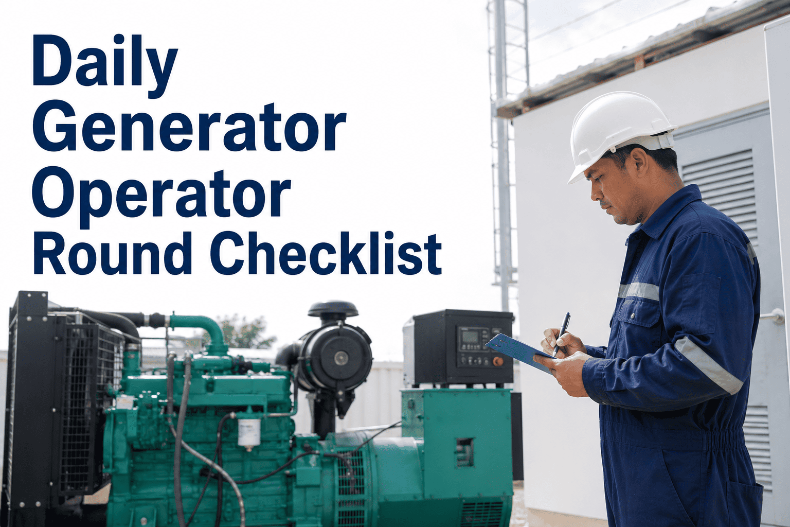
A generator can run with every gauge in the green while critical failures develop silently over weeks. Rising partial discharge, dropping hydrogen purity, unstable field current, or increasing stator water conductivity can lead to catastrophic rewind costs of $400,000–$600,000 if missed. This checklist covers the daily parameters operators must log and trend for large hydrogen-cooled turbine generators — including hydrogen purity, seal oil, stator water system, AVR and field current, exciter brush gear, stator winding temperatures, and CMMS sign-off. OxMaint's generator round module captures readings on mobile, trends shift-over-shift data, and automatically generates audit-ready compliance records. Book a demo to see live generator round workflows in OxMaint.
Checklist · Power Plant Generator · Daily Operator Round · NERC PRC-005
Daily Generator Operator Round Checklist for Power Plants
Hydrogen purity, seal oil differential, stator cooling water, AVR and field current, exciter brush gear, winding temperatures, and CMMS sign-off — the complete daily round framework for hydrogen-cooled turbine generators.
67%
of generator forced outages begin with gradual, detectable degradation that daily rounds can catch
97%+
Minimum hydrogen purity required for safe operation — below 75% enters flammable range
$480K
Average stator emergency rewind cost — preventable with early stator temperature and partial discharge trending
NERC PRC-005
Requires documented maintenance records for all generator protection systems — AVR, relays, and exciter
Generator Daily Round — Six Subsystem Areas
H₂
Hydrogen & Seal Oil
Critical — explosion risk below 75% purity
H₂O
Stator Cooling Water
High — conductivity rise signals insulation contamination
AVR
AVR & Field Current
High — voltage instability precedes grid stability events
EXC
Exciter & Brush Gear
Medium-High — brush wear causes field current loss
°C
Stator Winding Temps
Critical — hotspot above 130°C accelerates insulation ageing 2x per 10°C
LOG
Shift Sign-off & CMMS
Compliance — NERC PRC-005 and OSHA 1910.269 audit trail
Area 01
Hydrogen Purity, Pressure & Seal Oil System
Hydrogen cooling in large turbine generators (typically 200 MW and above) is used because hydrogen has seven times the thermal conductivity of air and dramatically lower windage losses. But hydrogen introduces a unique safety requirement: purity must remain above 97% at all times during operation. Between 4% and 75% hydrogen concentration in air is the flammable range. A generator operating with degraded hydrogen purity is not just less efficient — it is a fire and explosion risk. The hydrogen seal oil system maintains a positive oil pressure differential above the hydrogen gas pressure at the shaft seals, preventing hydrogen from escaping along the shaft. If seal oil differential pressure is lost, hydrogen leaks to atmosphere and, in the presence of any ignition source in the generator hall, creates a life-safety event.
Hydrogen & Seal Oil Checklist
Safety-Critical · Every Shift · No Exceptions
Hydrogen purity confirmed above 97% — purity reading from gas chromatograph or thermal conductivity analyser logged; any reading below 97% triggers investigation of seal oil system for oil carry-over into hydrogen gas; reading below 95% requires immediate notification of shift engineer; a purity reading below 90% is a gas replacement event per OEM emergency procedure — do not delay
Log: H₂ purity (%) and instrument ID · Standard: OEM spec / IEEE 1129 · Role: Generator Operator · Frequency: Every shift
Hydrogen casing pressure confirmed within operating range — gas pressure at casing confirmed at set operating pressure (typically 3–5 bar absolute for large units); any unexplained pressure drop without a corresponding purity change indicates an external casing leak — pressurised hydrogen leak on an operating machine is a category-one safety event; adjacent work permits suspended and area cleared until source located
Log: H₂ casing pressure (bar abs) · Standard: OEM operating manual · Role: Generator Operator · Frequency: Every shift
Seal oil differential pressure confirmed — seal oil supply pressure confirmed tracking above hydrogen casing pressure by the required differential (typically 0.5–0.8 bar above gas pressure); seal oil DE and NDE bearing differential pressures both logged; any differential pressure drop to zero means hydrogen is escaping at that shaft seal — immediate emergency response required; seal oil pump auto-start status confirmed on DCS
Log: Seal oil differential pressure (bar) at DE and NDE seals · Standard: IEEE 1129 · Role: Generator Operator · Frequency: Every shift
Hydrogen dryer and liquid detector checked — hydrogen dryer in service and desiccant condition confirmed not saturated (sight glass colour indicator blue, not pink); liquid level detector at bottom of generator casing confirmed reading dry — any liquid accumulation in generator casing indicates seal oil carry-over or stator water leak, both of which degrade hydrogen purity and insulation condition
Log: Dryer status and liquid detector reading (Dry / Liquid present) · Role: Generator Operator · Frequency: Every shift
Hydrogen make-up consumption rate reviewed — daily hydrogen consumption logged from supply cylinder or bulk supply pressure drop; consumption significantly above the plant's established normal baseline indicates developing leak in casing seals, cooler tubes, or bushing penetrations; rising make-up consumption over three consecutive shifts triggers a formal leak detection survey logged as a work request in OxMaint
Log: H₂ consumption (m³/day or supply pressure drop) · Role: Generator Operator / Engineer · Frequency: Daily
Area 02
Stator Cooling Water System Checks
In large water-hydrogen-cooled generators, the stator windings are hollow copper conductors through which demineralised cooling water is circulated under pressure. The stator water system is the most direct interface between the electrical insulation of the stator and a conductive fluid — and the conductivity of that fluid is the daily round's most important electrical safety parameter. Conductivity above 2 µS/cm indicates mineral contamination or mixed-bed resin exhaustion in the cooling water treatment system. Contaminated stator water in contact with the winding insulation causes surface leakage current, insulation tracking, and eventually a stator winding ground fault that requires an emergency rewind.
Stator Cooling Water Checklist
Every Shift · Conductivity is the Key Indicator
Stator water conductivity confirmed within limit — conductivity reading from inline analyser or grab sample below 0.5 µS/cm (OEM typical limit; EPRI guideline is below 2 µS/cm); conductivity above 1.0 µS/cm triggers mixed-bed resin check and replacement scheduling; conductivity above 2.0 µS/cm is an amber alert — load reduction should be discussed with shift engineer; conductivity above 5 µS/cm warrants consideration of emergency shutdown for water system investigation
Log: Stator water conductivity (µS/cm) and instrument calibration date · Standard: EPRI TR-1010678 / OEM manual · Role: Generator Operator / Chemist
Stator water inlet and outlet temperatures logged — inlet temperature confirmed within OEM range (typically 35–45°C); temperature differential between inlet and outlet logged; reduced delta-T at the same flow rate indicates a blocked winding strand — a blocked stator bar reaches thermal runaway and burns through within minutes at full load; any reduced delta-T triggers immediate engineering notification
Log: Inlet temp (°C), outlet temp (°C), delta-T · Standard: OEM operating manual · Role: Generator Operator · Frequency: Every shift
Stator water flow rate and pressure confirmed — total system flow within OEM specified range; no flow alarm active; stator water pump running and standby pump on auto-start confirmed on DCS; differential pressure across stator winding headers within normal range — elevated differential pressure across the winding indicates partial blockage in hollow strand conductors
Log: Stator water flow (l/min or m³/hr) and system pressure · Role: Generator Operator · Frequency: Every shift
Stator water tank level and oxygen content checked — header tank or expansion vessel level within normal operating band; dissolved oxygen in stator water within OEM limit (typically below 200 ppb for copper strand generators to prevent copper oxide corrosion); oxygen scavenger dosing confirmed running; any tank level drop exceeding 5% without maintenance activity indicates an internal winding water leak into the generator casing
Log: Tank level (%) and dissolved O₂ (ppb) where monitored · Standard: EPRI guidelines · Role: Generator Operator / Chemist
OxMaint logs stator water conductivity, hydrogen purity, and winding temperatures against configurable shift limits — auto-raising maintenance work requests when readings trend toward alarm thresholds, so your team acts before the protection relay does.
Area 03
AVR Performance & Field Current Monitoring
The Automatic Voltage Regulator (AVR) maintains generator terminal voltage within limits by continuously adjusting the excitation current supplied to the rotor field winding. In grid-connected operation, the AVR also controls reactive power (MVAR) output. Under NERC PRC-005, the AVR and its associated protection functions — including field forcing, overexcitation limiter, and underexcitation limiter — are classified as generator protection system components requiring documented maintenance at specified intervals. The daily round is not a relay test — it is an operational verification that the AVR is performing stably, that field current matches the expected value for current MW and MVAR output, and that no excitation system alarms are active.
AVR & Field Current Checklist
NERC PRC-005 · Every Shift · Stability Verification
Generator terminal voltage confirmed within normal operating band — terminal voltage on DCS or panel meter within ±5% of rated voltage at current load; no voltage oscillation or hunting visible on DCS trend in the last 4 hours; AVR confirmed in AUTO mode — manual AVR mode is not acceptable for sustained operation and must be logged as a deviation with planned return to AUTO timeline
Log: Terminal voltage (kV) and AVR mode (AUTO/MANUAL) · Standard: NERC PRC-005 · Role: Generator Operator · Frequency: Every shift
Field current confirmed consistent with MW and MVAR output — field current reading on DCS compared to expected value from generator capability curve at current operating point; field current more than 5% above or below expected value at current MW/MVAR indicates AVR gain drift or excitation system problem; field current trending upward at constant MW/MVAR output indicates rotor winding resistance change — flag for engineering review
Log: Field current (A), MW output, MVAR output · Standard: IEEE C50.13 · Role: Generator Operator · Frequency: Every shift
No AVR or excitation system alarms active — DCS and local excitation panel checked for any active alarms; specific alarms requiring immediate action: field current limiter active, overexcitation limiter active, exciter diode fault (for brushless exciters), AVR tracking fault, and power system stabiliser (PSS) disabled; any active excitation alarm logged and maintenance notified before end of shift
Log: Excitation system alarm status (None / Active alarms listed) · Role: Generator Operator · Frequency: Every shift
Power System Stabiliser (PSS) confirmed in service — PSS operational status confirmed on DCS; PSS out-of-service must be reported to system operator per grid code requirements in most jurisdictions; PSS offline for more than one shift requires shift engineer notification and grid operator report per NERC PRC-019 requirements; PSS reconnection target time documented in OxMaint
Log: PSS status (In service / Out of service + reason) · Standard: NERC PRC-019 · Role: Generator Operator / Shift Engineer
Area 04
Exciter & Brush Gear Inspection
Generators with slip-ring brush gear (static excitation systems and some older designs) require visual inspection of carbon brushes, slip rings, and brush holders every shift. Carbon brushes wear continuously during operation — a brush worn to its minimum length (typically 25mm for most designs) loses spring pressure contact, causes arcing at the slip ring surface, and ultimately results in field current interruption. Field current loss on a loaded generator causes an immediate under-excitation trip and, depending on the grid connection configuration, can cascade into a grid disturbance. Brushless excitation systems (rotating rectifiers) do not have this failure mode but require diode rectifier health monitoring instead.
Exciter & Brush Gear Checklist
Every Shift · Brush Length Critical
Carbon brush length measured and recorded for all brush holders — brush length confirmed above minimum service limit (typically 25–30mm depending on OEM; below 20mm is a replace-now condition); brushes showing heat discolouration, chipping, or cracking replaced immediately; brush seating surface contact area confirmed above 80% of brush face area — poor seating causes arcing and slip ring surface damage
Log: Brush length (mm) per holder — minimum length triggers OxMaint work request automatically · Role: Generator Operator · Frequency: Every shift (slip ring type)
Slip ring surface condition inspected — slip ring surface confirmed smooth and uniformly polished; no pitting, grooving, flat spots, or discolouration indicating arcing; no carbon dust accumulation on brush holder insulation that could cause tracking; any surface irregularity that cannot be corrected by light dressing during operation flagged for outage repair planning; slip ring temperature confirmed below 80°C by IR measurement where accessible
Log: Slip ring surface condition (Good / Pitting / Grooving / Arcing evidence) · Role: Generator Operator · Frequency: Every shift
Exciter output voltage and current confirmed — exciter terminal voltage and current output logged; for brushless exciters, any diode fault alarm on the rotating rectifier monitoring system logged immediately; exciter cooling air temperature and flow confirmed within range; exciter bearing temperatures logged per the bearing monitoring procedure; any exciter bearing temperature rise treated with same urgency as main machine bearing
Log: Exciter voltage (V), current (A), bearing temps (°C) · Role: Generator Operator · Frequency: Every shift
Daily Round — Key Parameter Limits at a Glance
H₂ Purity
>97%
<95%
<90% — gas replace
Seal Oil Differential
0.5–0.8 bar above gas
<0.3 bar differential
Zero differential — H₂ release
Stator Water Conductivity
<0.5 µS/cm
>1.0 µS/cm
>5.0 µS/cm — consider trip
Stator Winding RTD Temp
<115°C
>120°C or 5°C phase imbalance
>130°C — load reduction
Brush Length (slip ring)
>30mm
25–30mm — schedule change
<20mm — replace now
H₂ Cooler Delta-T
Per load curve
Reduced delta-T at same load
Zero delta-T — blocked cooler
Area 05
Stator Winding Temperature & Hydrogen Cooler Checks
Stator winding insulation life follows the Arrhenius thermal ageing law — every 10°C rise in operating temperature above the rated class temperature halves the insulation's remaining service life. A Class F insulation system rated at 155°C operating at 165°C ages twice as fast as the design assumes. The daily round RTD check is not just a thermal protection verification — it is the most direct indicator of both winding loading and cooling system performance. A winding temperature that is higher than expected at current load, or that shows a greater-than-5°C phase-to-phase imbalance between slots, is telling the operator that either the load distribution is unequal or the cooling is degraded. Both conditions require investigation before the next shift.
Stator Temperature & Cooler Checklist
Every Shift · Phase Balance Check Mandatory
All stator winding RTD readings logged and phase balance confirmed — temperature for each RTD recorded; maximum winding temperature confirmed below alarm setpoint; phase-to-phase temperature differential confirmed below 5°C; any single RTD showing more than 10°C above the average of all RTDs at the same axial location flagged as a potential hotspot; hotspot above 130°C (Class F) is a load reduction event
Log: All RTD readings (°C) and max-to-min spread · Standard: IEEE C50.13 / IEC 60034-1 · Role: Generator Operator · Frequency: Every shift
Hydrogen cooler performance confirmed — cooling water inlet and outlet temperatures logged for all cooler sections (typically 4 coolers on a large unit); temperature differential across each cooler compared to previous shift at same load — reduced delta-T indicates fouling of cooler tubes and degraded heat transfer; cooling water flow confirmed and any isolated cooler section logged with reason and load restriction applied
Log: Cooler CW inlet/outlet temps (°C) per cooler section · Role: Generator Operator · Frequency: Every shift
Rotor winding temperature indicator (if fitted) or field current-based rotor temperature estimate reviewed — rotor winding temperature by resistance method or RTD confirmed below OEM limit; rotor temperature significantly above expected for current field current suggests developing inter-turn short in rotor winding; rotor winding temperature trend reviewed across last 7 days in OxMaint before signing off round
Log: Rotor winding temp (°C) or field current and calculated resistance · Standard: IEEE C50.13 · Role: Generator Operator / Engineer
Generator bearing temperatures logged — DE and NDE generator bearing metal temperatures recorded and compared to previous shift; any temperature trend matched against turbine bearing data to distinguish between machine-specific and unit-wide lube oil issues; generator bearings share the turbine lube oil system on most designs — an oil pressure anomaly affects both machines simultaneously
Log: Generator bearing temps (°C) DE and NDE · Role: Generator Operator · Frequency: Every shift
Area 06
Shift Sign-off & NERC Compliance Documentation
Generator operator round records are not optional documentation — they are the evidence base for NERC PRC-005 protection system maintenance compliance, insurance risk assessment, and OEM warranty validity. Under NERC PRC-005, any generator protection system component (including AVR protective functions, field current limiters, and loss-of-excitation relays) that cannot demonstrate a documented maintenance history within the applicable maintenance interval is out of compliance — regardless of whether it is functional. OxMaint generates the complete NERC PRC-005 evidence report from round records and maintenance work orders, exportable on demand in under two minutes.
Shift Sign-off & Compliance Checklist
NERC PRC-005 · Every Shift · Audit Trail Required
All round parameters confirmed entered in OxMaint — H₂ purity, seal oil differential, stator water conductivity, AVR mode and voltage, field current, brush lengths (if applicable), stator RTD readings, cooler temperatures, and bearing temperatures all logged with timestamps; system enforces 100% completion before sign-off proceeds; any reading in amber or red status requires comment before sign-off is accepted
Log: OxMaint round completion status — 100% fields required · Role: Generator Operator · Frequency: Every shift
NERC reportable conditions confirmed — any condition requiring NERC event reporting (protection system operation, AVR out of service, PSS out of service, generation trip) confirmed reported or confirmed not present; OxMaint shift summary flags any parameter that crossed alarm threshold during shift for inclusion in shift report; nothing self-resolving during a shift may be omitted from the handover record
Log: NERC reportable event status (None / Listed) · Standard: NERC PRC-005 / NERC EOP-004 · Role: Generator Operator + Shift Engineer
Incoming operator formally accepts generator in OxMaint — incoming operator reviews H₂ purity trend, open maintenance work requests, and any equipment with restrictions; accepts the unit with authenticated sign-on; any generator operating under a derating or with a protection system component out of service must be explicitly re-confirmed by the incoming operator before the outgoing operator signs off
Log: Both operator IDs with timestamps · Role: Both operators · Frequency: Every shift change
Documentation Requirements — Generator Daily Round Records
| Record Type |
Required Content |
Retention |
Standard |
OxMaint Module |
| Hydrogen purity & pressure log |
Purity %, casing pressure, make-up consumption, seal oil diff, timestamp |
5 years |
IEEE 1129 / OEM manual |
Round sheet — every shift |
| Stator water chemistry log |
Conductivity, inlet/outlet temps, flow rate, dissolved O₂, tank level |
5 years |
EPRI TR-1010678 |
Chemistry module — mandatory gate |
| AVR & excitation log |
Terminal voltage, AVR mode, field current, MW/MVAR, PSS status |
5 years |
NERC PRC-005 / IEEE C50.13 |
Round sheet — NERC flag auto-applied |
| Brush gear inspection record |
Brush length per holder, slip ring condition, exciter bearing temps |
3 years |
OEM maintenance manual |
Round sheet — length vs limit auto-check |
| Stator RTD temperature log |
All RTD readings, max temp, phase-to-phase delta, cooler performance |
5 years |
IEC 60034-1 / IEEE C50.13 |
Round sheet — thermal trend chart |
| Shift handover record |
Both operator IDs, open WOs, NERC reportable events, equipment restrictions |
3 years |
NERC PRC-005 / OSHA 1910.269 |
Handover module — dual sign-off |
Frequently Asked Questions
What is the minimum safe hydrogen purity for an operating turbine generator?
Hydrogen must be maintained above 97% purity during operation. Below 75% hydrogen concentration in air is the lower explosive limit — operation between 4% and 75% hydrogen in air creates a flammable mixture. OEM operating procedures typically require a gas replacement purge (via CO₂) if purity falls below 90%.
OxMaint's round sheet auto-raises a critical alert if purity drops below the configured threshold.
Why does stator water conductivity matter so much for generator safety?
Stator cooling water flows through the hollow copper conductors of the stator winding. If water conductivity rises above safe limits, current leaks through the cooling water itself to ground, degrading insulation and eventually causing a stator ground fault. A stator ground fault on a loaded generator typically requires an emergency rewind, costing $400,000–$600,000 and taking 4–8 weeks. Daily conductivity checks are the primary prevention tool.
What NERC standard applies to generator daily round records?
NERC PRC-005 (Protection System, Automatic Reclosing, and Sudden Pressure Relaying Maintenance) requires documented maintenance records for all generator protection system components, including AVR protective functions, field current limiters, and loss-of-excitation relays. Daily round records that document AVR status and field current contribute to the evidence base for PRC-005 compliance audits.
OxMaint generates the full PRC-005 evidence report on demand.
How frequently should carbon brushes be inspected on a slip-ring generator?
Carbon brush length should be checked every shift on operating generators with slip-ring excitation. Brush wear rate depends on load, current density, and slip ring surface condition. Any brush below 25mm requires a change request; below 20mm is a replace-immediately condition. Brush changes on operating generators are performed by qualified personnel following the plant's hot work procedure.
What does a phase-to-phase stator RTD temperature imbalance indicate?
A stator RTD imbalance greater than 5°C between slots in the same phase region indicates either unequal load distribution in the winding or localised cooling degradation. An imbalance exceeding 10°C above the average of all RTDs at the same axial position indicates a potential hotspot — a developing insulation failure or blocked cooling strand — and requires engineering review before the next shift.
OxMaint's thermal trend chart displays all RTD readings and flags imbalances automatically.
OXMAINT FOR POWER PLANTS · GENERATOR DAILY ROUNDS
Log H₂ Purity, Stator Water, AVR Status & Winding Temps Every Shift — Zero Paperwork, Full Audit Trail.
OxMaint's generator round module enforces complete shift data entry, trends every parameter automatically, and generates NERC PRC-005 compliance reports on demand. From hydrogen seal oil to brush gear length — every reading in one platform.